How to Use the Basic Program 2. Program Change
NFS-640 Programming Manual P/N 51333:B 10/03/2003 25
How to Modify NAC and Panel Circuit Points
Modifying NAC (four NACs on the NFS-640) and Panel Circuits (connected through J5 or J6) is like
modifying control modules—except for the Type Code and device address.
To modify a point, follow these steps:
Note: A blinking cursor indicates the selected field.
1. From the programming screen, use the arrow keys to move to a field that you want to modify and
refer to information below for descriptions and settings.
Table 8 Modifying a NAC/Panel Circuit Programming Selections
2. When finished modifying a point, press the
ENTER key; then press the NEXT or PREVIOUS key to
select another point.
The address of a NAC connected
through NAC 1 (B01), NAC 2
(B02), NAC 3 (B03), or NAC 4
(B04); or the address of a Panel
Circuit connected through J5 or J6
(for example, P1-2 represents
Panel Circuit module 1, circuit 2).
Five zones for CBE list; the default zone
selection is 00 (general alarm)
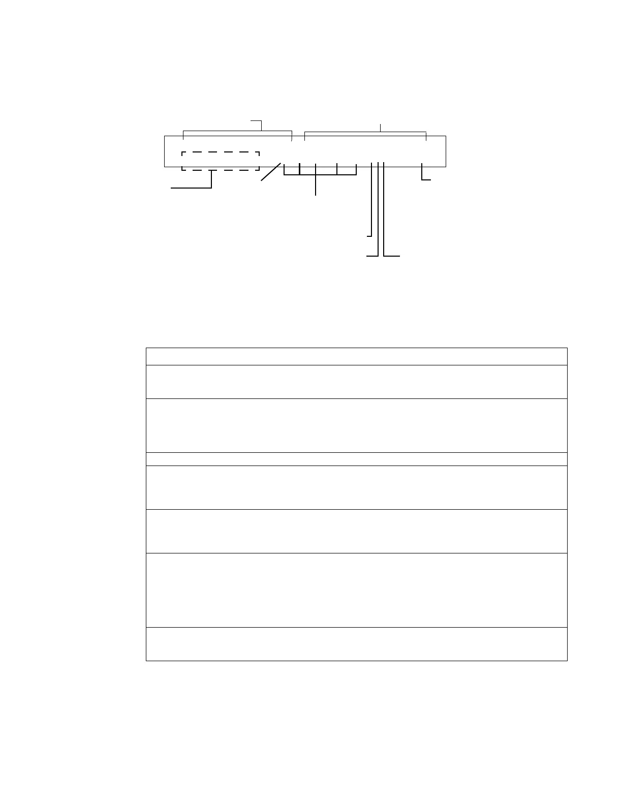
PROGRAM CONTROL PANEL CKT NO.1 BELLS
00 __ __ __ __ *SW B01
Default zone
12 spaces for extended
custom label
Switch Inhibit: I=selected; *=off (default)
Walk Test Selection: *=off (default);
W=selected
Silenceable: S=selected; *=off (default)
Type Code
20-character user-editable custom label
Field Description Set as follows:
Type Code Specifies the function of the NAC or Panel
Circuit
Press the NEXT or PREVIOUS Selection keys to scroll through
the NAC or Panel Circuit Type Code selections (listed in
Table 35 on page 107)
Custom Label 20 character custom label. Change by placing the cursor into the first space of the field
using the arrow keys, then typing the descriptor.
Note: Spaces must be input by the user, including any space
necessary between the custom and extended label fields. An
80-column printout will run the two fields together.
Extended Label 12 character custom label extension. See “Custom Label” above.
CBE zones Specifies up to five software zones to define
the output responses of the NAC or Panel
Circuit based on various initiating
conditions (events)
Type the numbers of up to five zones, including E0-E9, F0-
F9, L0-L9, R0-R9, and zones 00-99. The first zone default is
00 (general alarm)
Switch Inhibit Specifies if an operator can manually
activate an output
Type in one of the following values.
I = Switch Inhibit enabled
* = Switch Inhibit disabled (default for all but releasing
circuits)
Silenceable Specifies if an operator can manually
silence an activated output
Type in one of the following values.
* = output nonsilenceable
F = silenceable, resound by fire alarm
U = silenceable, resound by supervisory alarm
B = silenceable, resound by security alarm
T = silenceable, resound by trouble
O = silenceable, does not resound
Walk Test Specifies if outputs sound during Walk Test Type in one of the following values.
W = devices sound (Basic Walk Test) - default
* = devices do not sound (Silent Walk Test)
www.PDF-Zoo.com

 Loading...


