52 Rev 2.3 • 14 Oct 08
3. Installation
Making Signal Connections
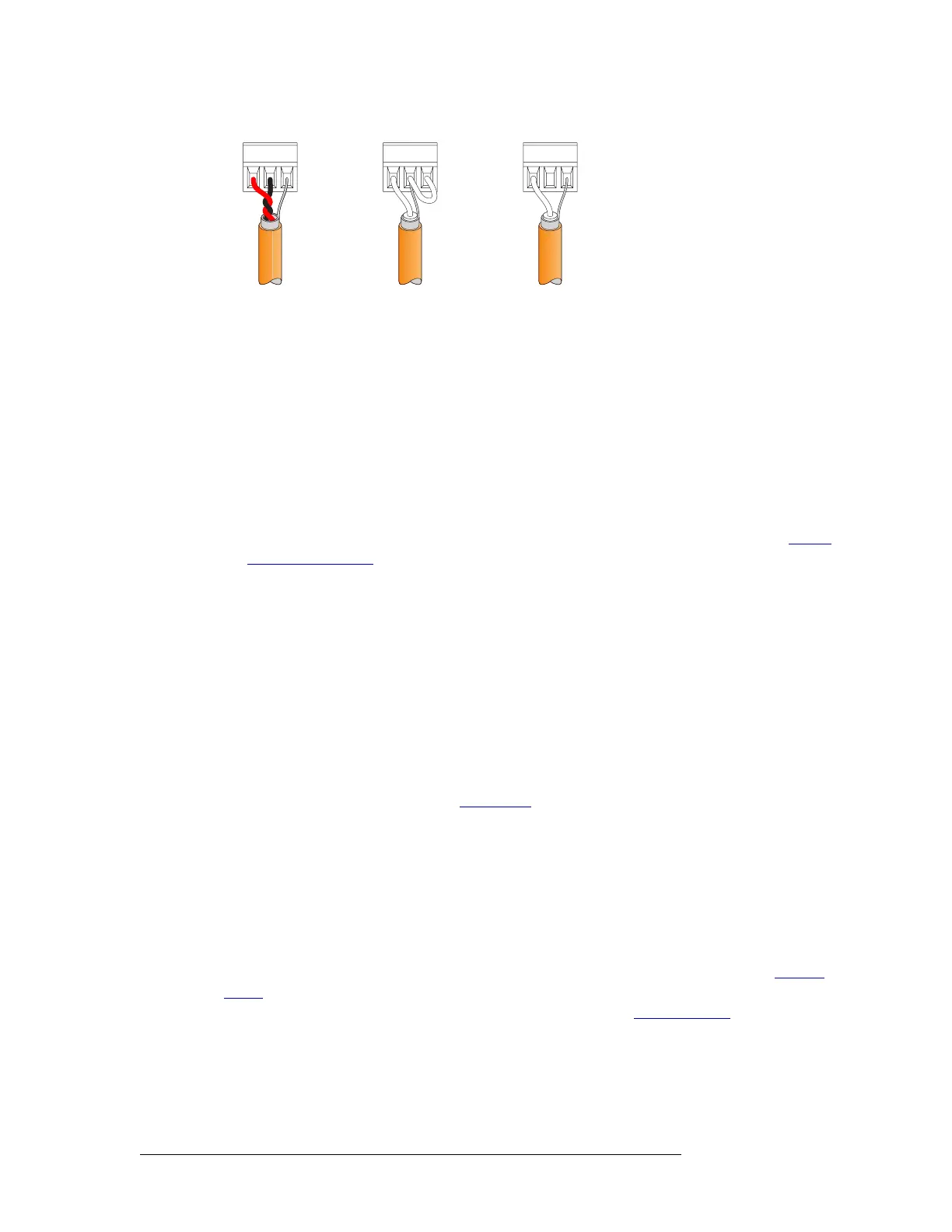
Figure 3-9. Phoenix Connectors and Connection Methods
How to make connections for AES signals
1 Locate the AES input connections at the rear of the router, as shown in Figure 3-8 on page 51.
There are 16 BNC connectors on each backplane for AES unbalanced signals and 16 Phoenix
connectors on each backplane for AES balanced signals.
2 For each input connection, connect using the connector and cable appropriate for the type of
incoming signal:
For AES unbalanced signals, use a BNC connector and 75
Ω cable.
For AES balanced signals, use a Phoenix connector and twisted-pair 110
Ω cable. See About
Phoenix Connectors on page 51.
3 Connect the other end of the cable to the source of the signal.
4 Locate the AES output connections on the rear of the router, as shown in Figure 3-8 on page 51.
5 For each output connection, connect using the connector and cable appropriate for the type of
outgoing signal as described in Step 2.
6 Connect the other end of the cable to the signal destination.
7 Make other signal connections, as needed.
Analog Signals
The NV5128 can manage analog signals. Signals are received and distributed through DB25 con-
nections, housed on backplanes. (See Backplanes
on page 13.)
Each backplane contains four DB25 connectors. Each connector supports either stereo or mono sig-
nals:
•Stereo
— 4 channel pairs, for a total of 16 stereo signals per backplane.
• Mono — 8 channels, for a total of 32 mono signals per backplane.
The DB25 connectors are labeled ‘1–4 Stereo’, ‘5–8 Stereo’, ‘9–12 Stereo’ and ‘13–16 Stereo’. The
labels correspond to the signal number assigned to the signals passing through that connector.
Analog signals are converted to digital (sample rate of 48kHz) for internal routing. (See Analog
Audio on page 25.) For proper conversion to occur, the system AES reference connection must be
connected. For instructions on connecting the AES reference, see AES Reference
on page 57.
The analog audio output card is designed to function in a voltage-matched system driving high-
impedance loads. The output drivers are not designed to drive 600
Ω loads continuously and may
overheat if used in a 600
Ω environment.
Balanced I/O
(Recommended)
Unbalanced Inputs
(Not Recommended)
Unbalanced Outputs
(Not Recommended)

 Loading...