NV5128 Multi-Format Router • User’s Guide 53
3. Installation
Making Signal Connections
Mono Signals
How the NV5128 switches mono signals is dependent upon the router control system. Before set-
ting up analog signals, make sure that the router control system can manage mono signals. All sig-
nal number labeling on the router frame refers to stereo signals, not mono signals. In order to
successfully install and implement the receiving and distributing of mono signals, great care should
be taken to avoid confusion. For more information on mono signals and signal number labeling, see
Mono Channels
on page 8.
Gain, Mute Detection and Operating Levels
When receiving and distributing unbalanced analog signals, a drop in level of 6 dB occurs. This is
due to one-half of the input signal being lost when the ‘-’ input is grounded and is normal. Using a
switch located on the analog audio input card, an additional 6
dB of gain can be added to compen-
sate for the drop. In addition, mute detection and operating levels can be set, ensuring a clearer
audio signal. For instructions on setting gain, mute detection and operating levels, see Analog
Audio Switches on page 69.
How to make connections for analog signals
1 Locate the analog input connections on the rear of the router, as shown in Figure 3-8 on page
51. There are four DB25 connectors on each analog backplane.
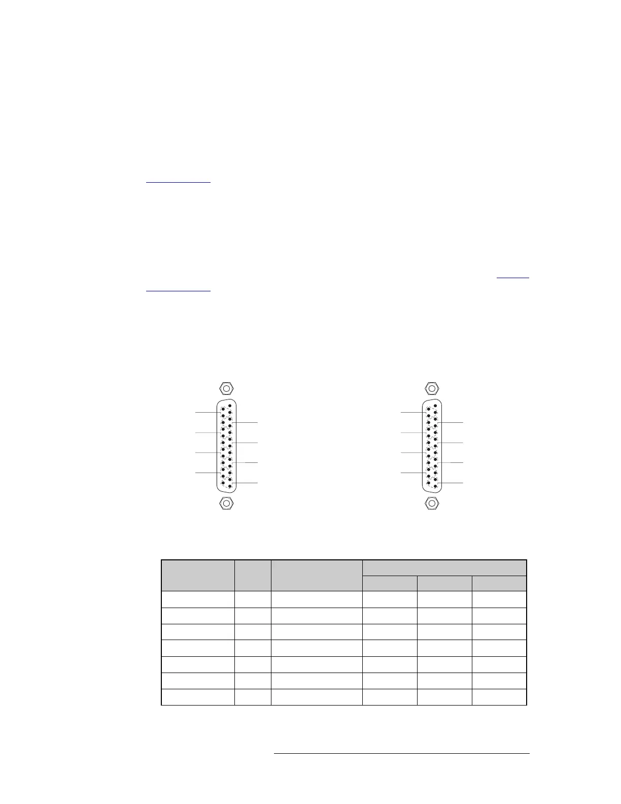
2 For each analog input, connect using a DB25 connector and cable, wiring the connectors as fol-
lows:
Figure 3-10. Mono Pin Assignments
An optional pre-made DB25 male to pigtail breakout cable is available from NVISION
(NV5000-Cable1). The wiring details for this cable are as follows:
13 Unused
Input 2
Input 4
Input 8
Input 6
11
23
10
8
20
7
5
17
4
2
14
1
Input 1
Input 3
Input 7
Input 5
25
12
24
22
9
21
19
6
18
16
3
15
1
14
25
SHLD
+
SHLD
+
SHLD
+
SHLD
+
SHLD
+
SHLD
+
SHLD
+
SHLD
+
13 Unused
1 Right
2 Right
4 Right
3 Right
11
23
10
8
20
7
5
17
4
2
14
1
1 Left
2 Left
4 Left
3 Left
25
12
24
22
9
21
19
6
18
16
3
15
1
14
25
SHLD
+
SHLD
+
SHLD
+
SHLD
+
SHLD
+
SHLD
+
SHLD
+
SHLD
+
Mono Stereo
Channel Pair Jacket Color
DB25 Connector Pin Number
Red (+) Black (–) GND
1 - Left 1 BROWN 24 12 25
1 - Right 2 RED 10 23 11
2 - Left 3 ORANGE 21 9 22
2 - Right 4 YELLOW 7 20 8
3 - Left 5 GREEN 18 6 19
3 - Right 6 BLUE 4 17 5
4 - Left 7 VIOLET 15 3 16