NV5128 Multi-Format Router • User’s Guide 71
4. Configuration
Setting Jumpers and Switches on Cards and Card Sets
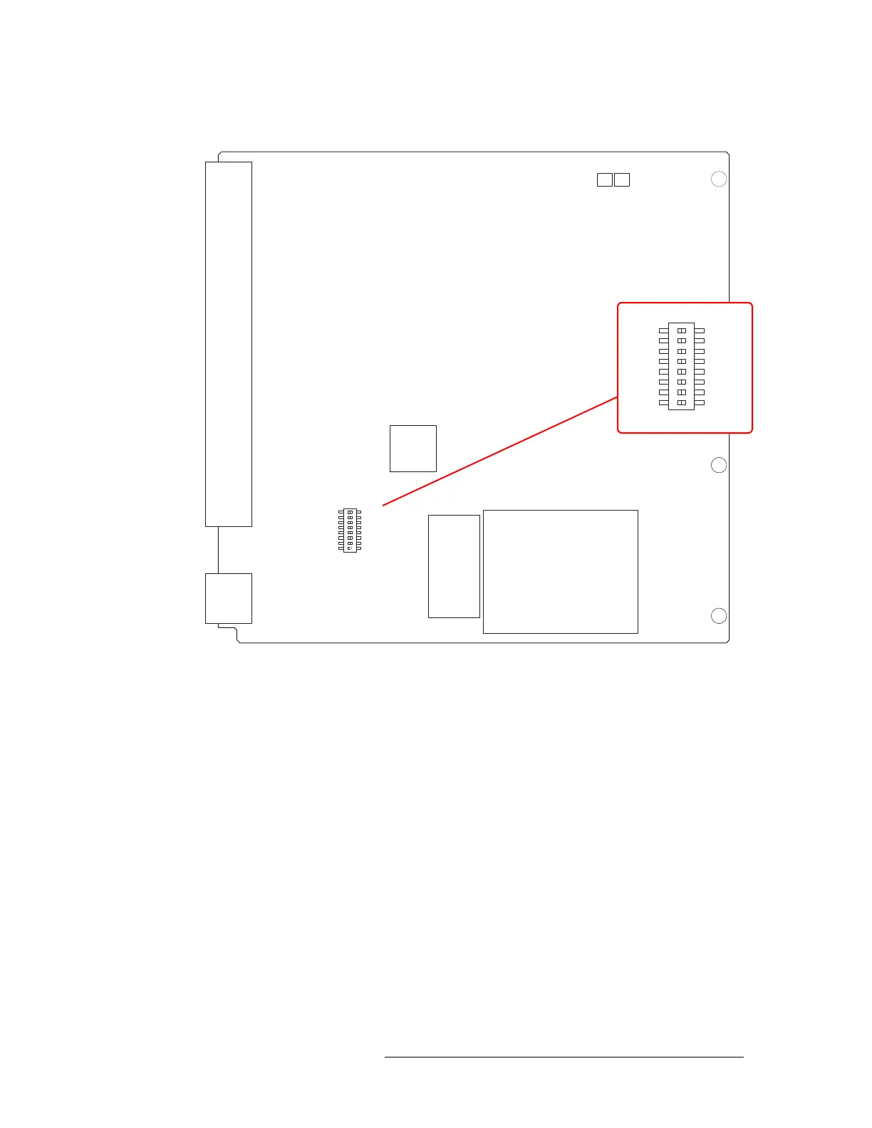
Figure 4-2 shows the location of the DIP switches for analog audio output card (EM0586):
Figure 4-2. Analog Audio Output Card Switch Locations
Analog Video Conversion (AVC) Card Switches
The AVC input card (EM0432) receives incoming composite analog video (NTSC or PAL) and
converts the signal to SD format for delivery to the motherboard. The AVC output card (EM0433),
receives SD formatted signals from the motherboard and converts them to composite analog video
outputs in NTSC or PAL formats. Because the color space for SD signals differs from that of com-
posite signals, the absence or presence of pedestal in NTSC signals must be accommodated if color
and luminance information is to be maintained. To accommodate these differences, DIP switches
are provided to preserve as best as possible the color and luminance integrity of signals processed
using AVC cards.
While composite PAL and NTSC inputs can be applied to and simultaneously routed by the AVC
input card (EM0432), all NTSC signals must be in the same format (NTSC-M or NTSC-J). The 8-
position DIP switch (S1) on the AVC input card configures the card to process NTSC signals cor-
rectly. If the incoming signals are NTSC-M formatted signals, set DIP Switch S1-1 to ON. The ON
position for S1-1 is determined by the markings on the body of the DIP switch. If the incoming for-
mat is NTSC-J (no pedestal), set S1-1 to OFF. The remaining seven switch positions (S1-2 through
S1-8) are not used. Switch S1-1 settings have no effect on PAL signal processing.
DIAGNOSTIC
1
2
3
4
5
6
7
8
OFF
ON
S1
EM0586-
NV5128 ANALOG AUDIO 16 STEREO OUTPUT
NVISION
PC0640-00
DIAGNOSTIC
1
2
3
4
5
6
7
8
OFF
ON
Operating Level