62 Rev 2.3 • 14 Oct 08
3. Installation
Making Diagnostic Connections
How to make GSC Node Bus connection to the router control system
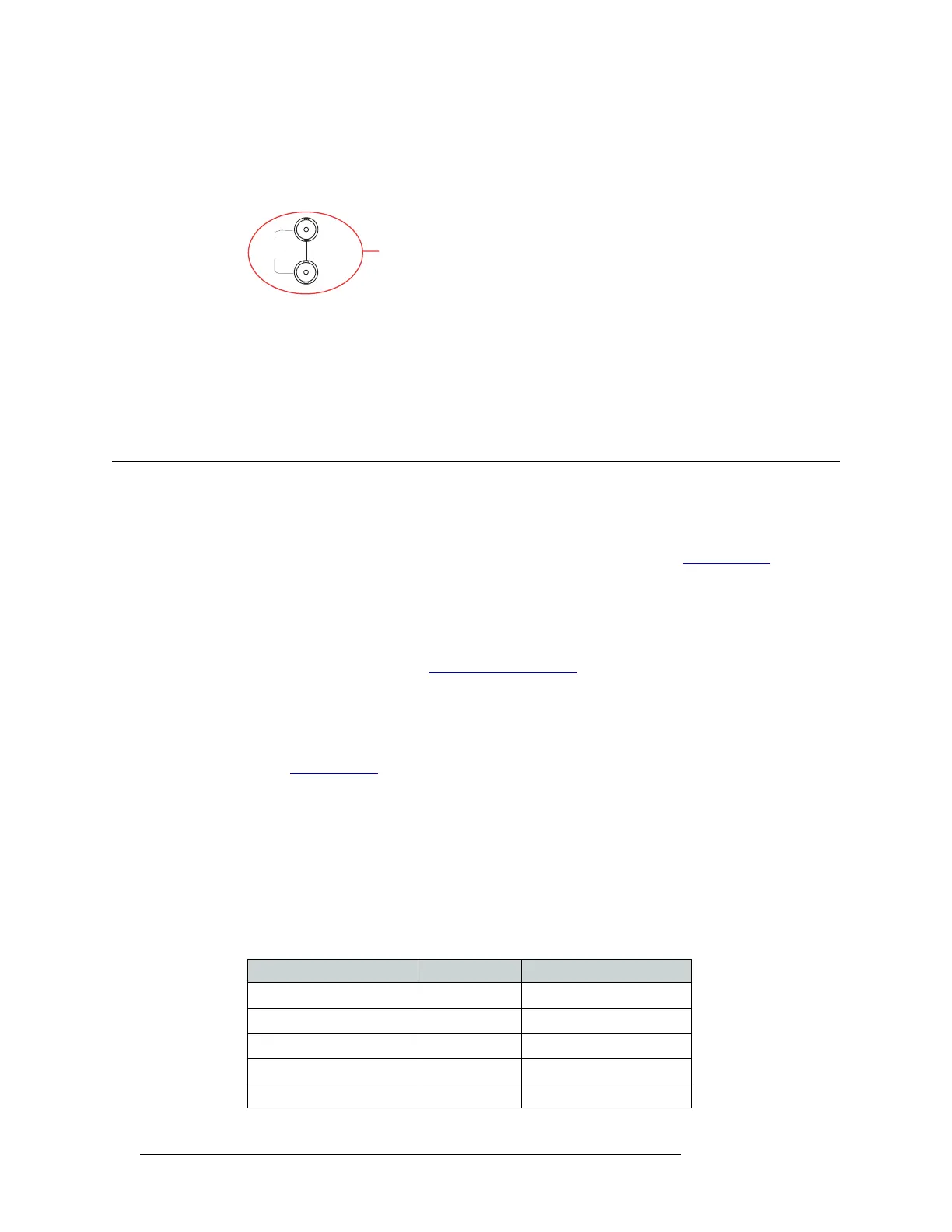
1 Locate the GSC Node Bus connection on the rear of the router, as shown in Figure 3-15. The
GSC Node Bus connection is labeled ‘NODE BUS’.
Figure 3-15. GSC Node Bus Connection to Control System (Rear View)
2 Connect to the ‘NODE BUS’ connection using a 75 ohm BNC connector and coaxial cable.
3 Connect the other end of the coaxial cable to the router control system.
4 Important: Install a 75
Ω BNC terminator on any unused GSC Node Bus loop-through connec-
tions.
Making Diagnostic Connections
The diagnostic connections enable the NV5128 to communicate with the UniConfig application.
UniConfig is installed on hardware (e.g., a PC), separate from the router, and is used to perform
system setup tasks, and configure and monitor the router. (See Chapter 4, Configuration
, on
page 67.) For information about using UniConfig, see the UniConfig User’s Guide.
There are two types of diagnostic connections: temporary and permanent. A temporary diagnostic
serial connection is located on the front of each control card. Permanent diagnostic serial connec-
tions are located on the rear of the router, labeled ‘DIAG’. For a detailed description of the perma-
nent diagnostic connections, see Diagnostic Connections
on page 18.
Temporarily Connecting to UniConfig
A temporary connection is created through the DE9 port located on the front of the primary control
card. (See Control Cards
on page 21.) This connection is set to RS-232, DTE, 9600 baud, 8 data
bits, no parity.
How to make a temporary diagnostic connection
1 Locate the primary control card slot, as shown in Figure 3-8 on page 51. When facing the front
of the router, the control cards are located in the upper, right-hand section.
2 On the front of the control card, connect to the DE9 connection using a DE9 connector and a
serial cable set for EIA-232.
The following lists the wiring for the DE9 pin connectors for RS-232:
LOOP
THRU
GSC Node Bus
Connection
to Control System
NODE
BUS
Hardware Pins Router
DCD 1 ------------1 Ground
RXD 2 ------------2 TXD
TXD 3 ------------3 RXD
DTR 4 ------------4 DSR
Signal Ground 5 ------------5 Signal Ground