NV5128 Multi-Format Router • User’s Guide 51
3. Installation
Making Signal Connections
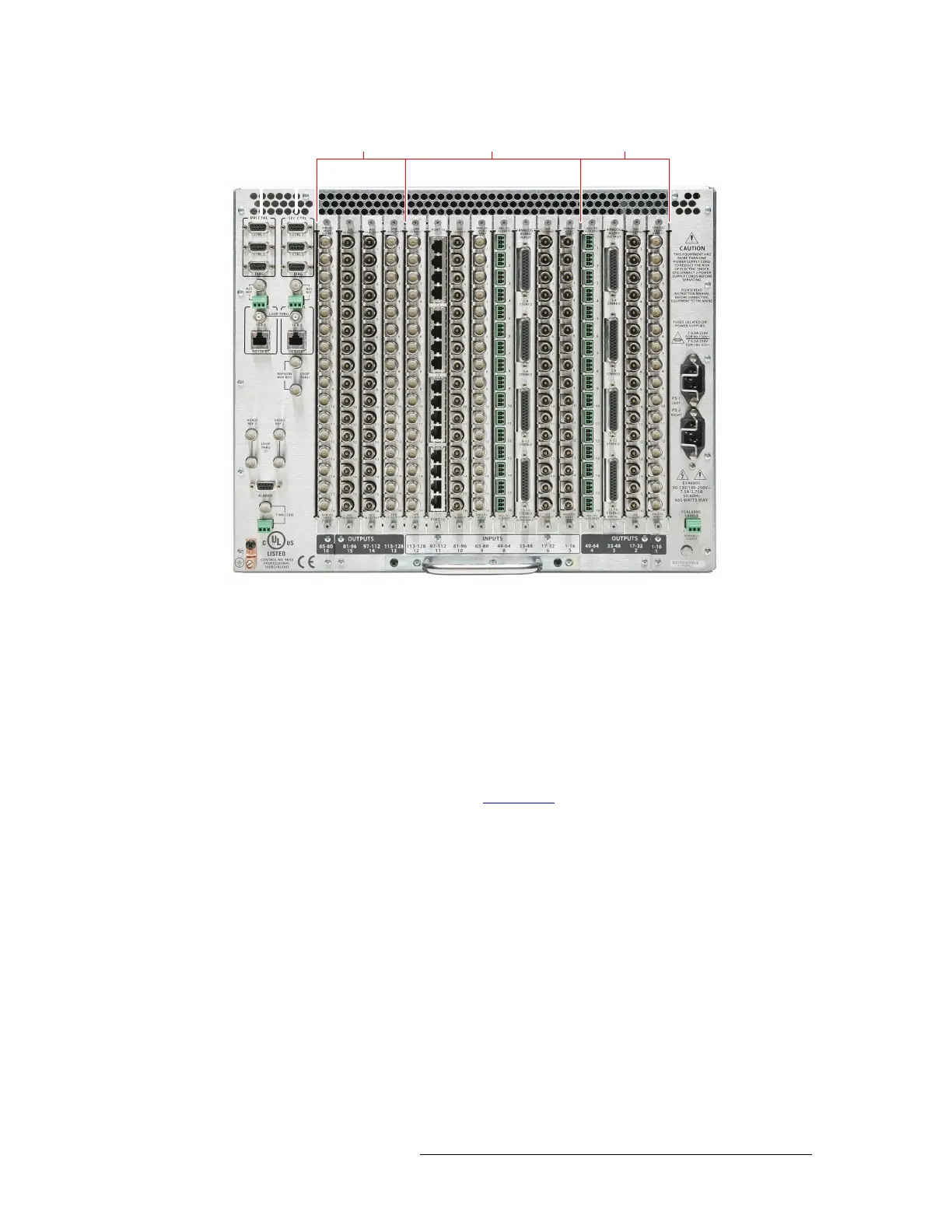
Figure 3-8. NV5128 Frame with Backplanes (Rear View)
Instructions for making signal connections are listed by signal type in the proceeding sections.
AES Synchronous Signals
The NV5128 can route both balanced and unbalanced AES synchronous signals. Unbalanced sig-
nals are received and distributed through BNC connectors. Balanced signals are received and dis-
tributed through Phoenix connectors. Both types of connectors are housed on backplanes located on
the rear of the router. Each backplane contains 16 connections labeled ‘1’, ‘2’ and so on up to ‘16’.
The labels correspond to the signal numbers assigned to the signal passing through that connector.
For more information on backplanes, see Backplanes
on page 13.
About Phoenix Connectors
Phoenix terminal blocks accept a stripped (bare) wire 18 AWG or smaller. The connectors plug into
the mating receptacle on the backplane, using friction to hold them in place.
When using Phoenix connectors, be sure that only the bare wire end is captive under the clamp
screw and that there are no stray strands that can cause short circuits or accidental ground connec-
tions. Also make sure that the weight of the cable or cable bundle does not cause the connector(s) to
disengage over time. Provide adequate support for the cables 12 to 18 inches from the rear of the
frame.
u
pu
–
npu
–
u
pu
–