68 Rev 2.3 • 14 Oct 08
4. Configuration
Setting Jumpers and Switches on Cards and Card Sets
Control Card Jumper Settings
The control card(s) (EM0374) contains several jumpers. Each jumper connection is labeled with a
jumper identification number. By default, jumpers are placed in the position most commonly used.
These jumpers must be set before the control card is placed into service.
The following lists each jumper label number, function, and correct setting. Any jumpers not listed
are unused and should be left in the factory position:
Classic SWB Card Set Jumpers
Classic SWB card sets (EM0395) automatically re-clock signals at 177, 270, 360, 540 or 1485 Mb/s.
If the data is at any other rate, the re-clocker automatically bypasses the signal, sending it to the
output without re-clocking it.
Individual output re-clockers on the Classic SWB card set can be selectively disabled and the signal
passed directly to the output. This can be done on an output-by-output basis using the UniConfig
application. For more information, see the UniConfig User’s Guide.
Jumper J21, located near the rear of the output module, under the mezzanine board, can be used to
configure the Classic SWB card set for DVB/ASI operation. The jumper (J21) is labeled DVB/ASI.
The default position is DISABLED, allowing normal SWB operation. When J21 is set to
ENABLED, the re-clockers are configured for DVB/ASI operation. In this mode, the re-clockers
ignore the 177
Mb/s sub-harmonic in the signal thereby re-clocking the signal correctly. When set
to DVB/ASI mode, the output re-clockers work properly with all standard SWB signals except
those at 177
Mb/s.
Standard SWB Jumpers
The SWB output cards (EM0463 and EM0465) each contain two jumpers. One jumper (J30) is
located near the front top edge of the board and is labeled RECLOCKER MODE. When the jumper
is in the AUTO position, the output re-clocker automatically re-clocks signals at 177, 270, 360, 540
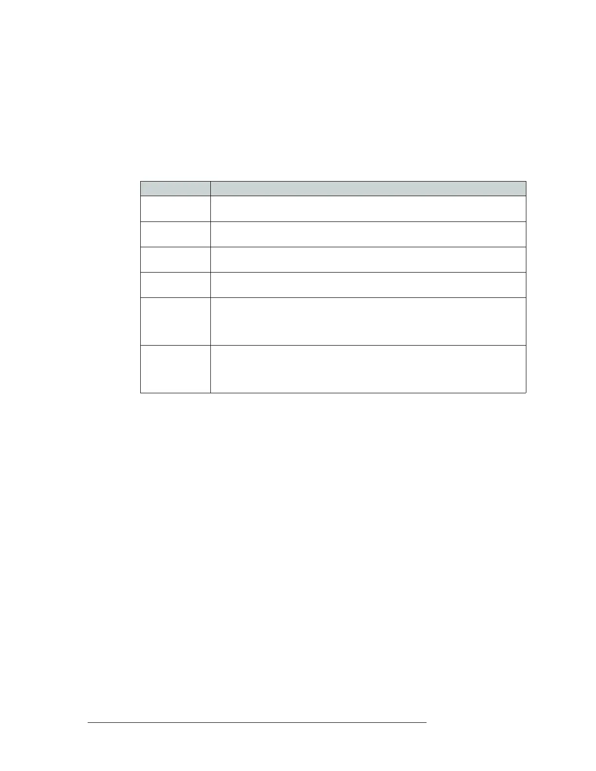
Jumper Label Settings
J1 SBUS/10B2 Sets rear connectors labeled 10Base2 to be used for Ethernet. Default set to lower
10Base2 position.
J2 SBUS/10B2 Sets rear connectors labeled 10Base2 to be used for Ethernet.Default set to lower
10Base2 position.
J4 SMS7/SBUS Sets rear Node Bus connectors to be used for third-party router control systems. Default
set to upper position.
J6 SMS7/SBUS Sets rear Node Bus connectors to be used third-party router control systems. Default set
to upper position.
J13 AES REF2 Sets the rear AES REF 2 input impedance to 110
Ω, 75 Ω, or Hi-Z (high impedance).
Upper position selects 110
Ω for use with Phoenix rear connectors, the middle position
selects 75
Ω for use with BNC rear connectors, or the lower position selects Hi-Z if this
input is the last connection in an equipment chain.
J16 AES REF1 Sets the rear AES REF 1 input impedance to 110
Ω, 7 Ω, or Hi-Z (high impedance).
Upper position selects 110
Ω for use with Phoenix rear connectors, the middle position
selects 75
Ω for use with BNC rear connectors, or the lower position selects Hi-Z if this
input is the last connection in an equipment chain.