56 Rev 2.3 • 14 Oct 08
3. Installation
Making Signal Connections
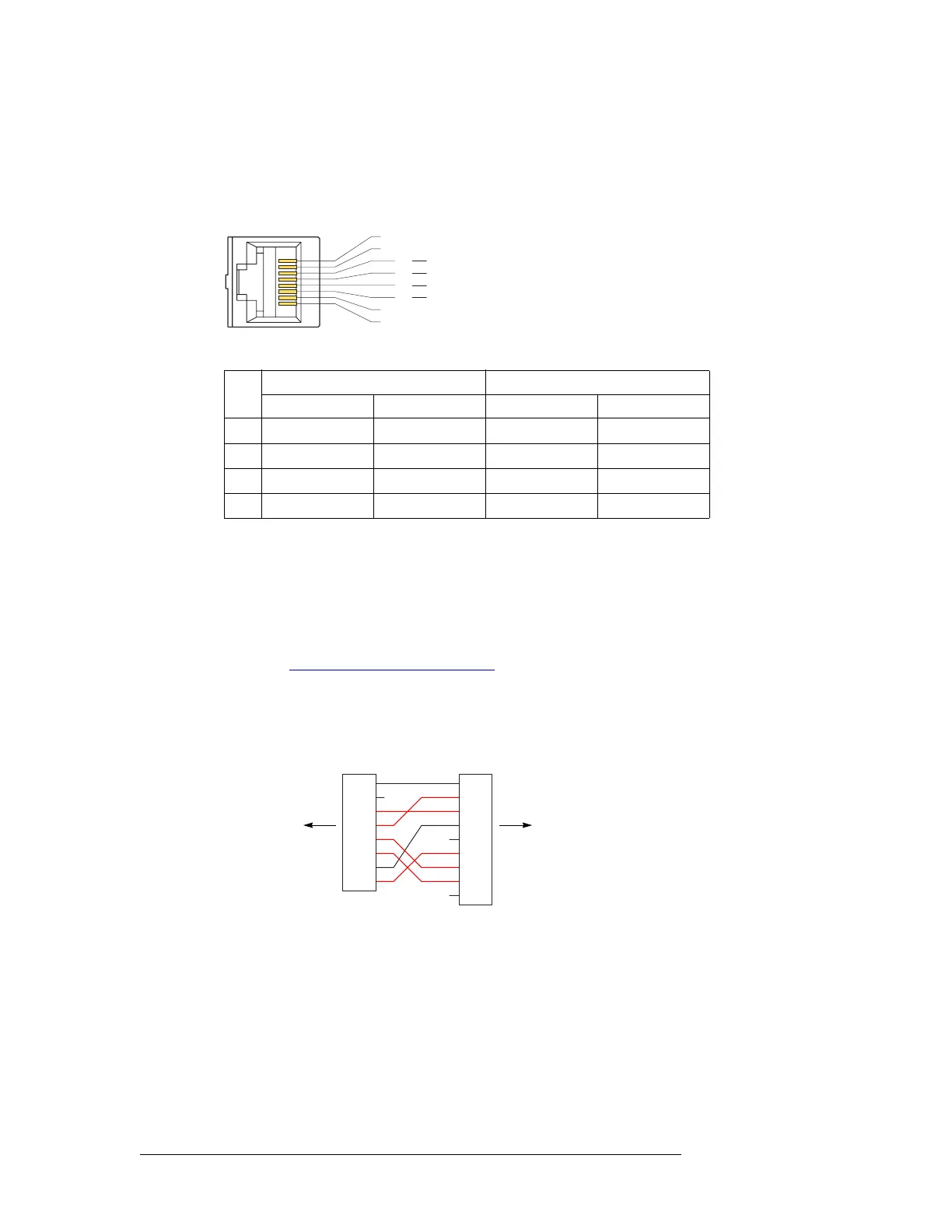
RJ-45 Connectors
The RJ-45 connectors are wired according to industry standard SMPTE 207M. For best perfor-
mance, use category 5 Ethernet cable and the proper tooling to ensure a secure and reliable connec-
tion when installing RJ-45 connectors. This is the connector pinout:
These are the functions of the pins:
(The other pins are grounded except for pin 2 which is not connected.)
DE9 Connectors
The machine control breakout panel (BP-PORT-64) has 64 RJ-45 connectors and 64 matching DE9
connectors. It lets you use DE9 cables to connect your machine control devices. The DE9 wiring
follows SMPTE-defined pin assignment standards. For more information on the converter back-
plane, see Machine Control Breakout Panel
on page 14.
If you are using the breakout panel, you might need to know the mapping of the signals from the
RJ-45 side to the 9-pin (female) side. The breakout panel is RS-422/485 only.
This is the RJ-45 to DE9 mapping for RS-422:
This cable wiring is applicable whether the port is a controlling port or controlled port.
S Older breakout panels might have incorrect wiring. Contact NVISION if your breakout panel
does not function correctly.
3
1
8
4
5
6
2 n.c.
1 Gnd
7 Gnd
8 Gnd
Tx +
Rx
Rx +
Tx
Rx +
Tx
Tx +
Rx
Controlling
Port
Controlled
Port
Pin
RS-422 RS-232
Controlling Controlled DTE DCE
3 Tx+ Rx+ Tx Rx
4 Rx– Tx– Gnd Gnd
5 Rx+ Tx+ Rx Tx
6 Tx– Rx– Gnd Gnd
1
2
3
4
5
6
7
8
9
RJ-45 DE9
1
2
3
4
5
6
7
8
to NV5128 backplane to your device