NV5128 Multi-Format Router • User’s Guide 65
3. Installation
Verification
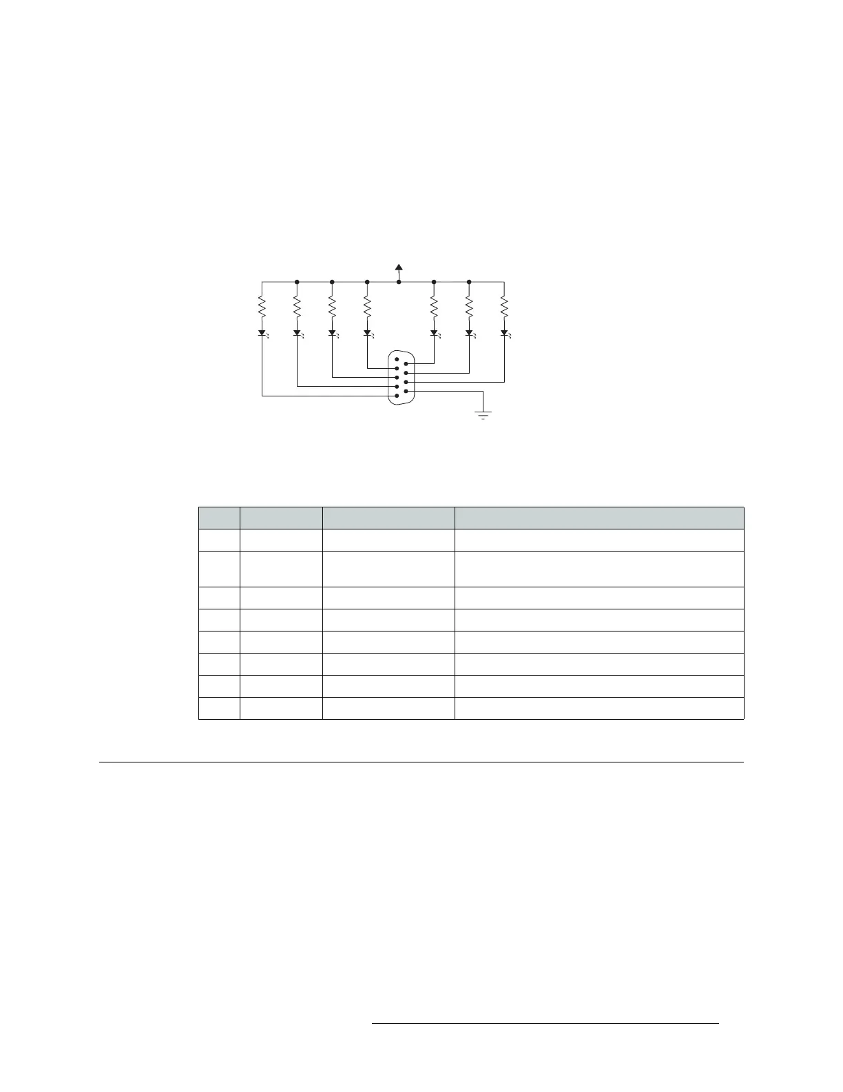
can be wired to specific pins on a DE9 connector. Each LED indicates what specific router module
has failed. An “alarm” or ON condition occurs when the connection between an alarm pin and
Alarm_COM (common) opens. The alarm turns OFF when the connection between Alarm_COM
and the alarm pin closes again.
To create an indicator box, connect to the ‘ALARM’ connection using a DE9 female connector,
wiring as shown in Figure 3-18. Each pin monitors a specific function and activates a specific
alarm.
Figure 3-18. Alarm Connections and On/Off Switches
The following lists each DE9 pin and the associated alarm. The pin number listed corresponds to
the pin numbers in Figure 3-18 on page 65:
Verification
When installation is complete, perform the following checks to make sure the router is operating
properly:
• On each PS6000 power supply module, check that all 5 green power LEDs on the front of each
module are lit. If any or all LEDs are off:
• Check that the power supply module is fully seated in its slot.
• Check the AC fuse on the power supply.
• Check for +48 volts at each of the 5 front test points.
1
Common
Internal alarm contacts
normally closed
Normally off, the
LEDs turn off to
indicate failure
30VDC max, 150mA max
External Power
Pin Signal Description Possible Conditions Causing the Alarm
1, 9 Alarm_COM Common Common connection for all alarm pins.
2 Alarm_1 Major alarm Indicates missing reference inputs, or missing power
supplies.
3 Alarm_2 Minor alarm Alarm_3, or Alarm_4, or Alarm_5, or Alarm_6
4 Alarm_3 Power supply Missing power supply module.
5 Alarm_4 Video ref Missing Video Ref 1 or Video Ref 2.
6 Alarm_5 AES ref Missing AES Ref 1 or AES Ref 2
7 Alarm_6 Fans or temperature Indicates a fan failure or module over temperature.
8 Alarm_7 Control module health Any control module not “healthy.”