NV5128 Multi-Format Router • User’s Guide 61
3. Installation
Making Router Control System Connections
Ethernet Router Control Connections
Ethernet router control connections connect the router to the router control system using Ethernet
connectors. Ethernet connections are helpful if the PC running the router control system is going to
be part of a network. An Ethernet connection is recommended for the NVISION NV9000 router
control system. The Ethernet ports are shared by the primary and secondary control cards. For a
detailed description of the Ethernet connections, see Ethernet Connections
on page 17.
In order for the router to communicate with the router control system through an Ethernet connec-
tion, an IP address for the router needs to be set in the control card. For more information, see the
UniConfig User’s Guide.
The Ethernet connections use RJ45 connectors and Category 5 Ethernet cable, or better. The Ether-
net port is 10/100
BT.
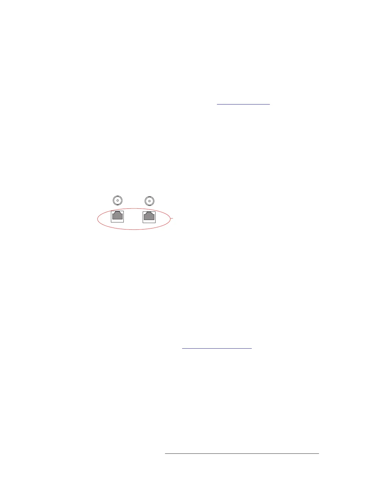
How to make an Ethernet connection to the router control system
1 Locate the Ethernet connections on the rear of the router, as shown in Figure 3-14. Ethernet
control connections are labeled ‘10/100 BASE T’.
Figure 3-14. Ethernet Connections to Router Control System (Rear View)
2 Connect to either ‘10/100 BASE T’ connection using a RJ45 connector and Category 5 Ether-
net cable, or better.
3 Connect the other end of the Ethernet cable to the primary router control system PC.
4 If a secondary (optional for redundancy) control card is installed, connect to the remaining ‘10/
100 BASE T’ connection using a RJ45 connector and Category 5 Ethernet cable, or better.
5 Connect the other end of the second Ethernet cable to the redundant router control system PC.
GSC Node Bus Router Control Connections
Some third-party router control systems require a GSC Node Bus connection to connect the router
to the router control system. The NV5128 has one GSC Node Bus connection, labeled ‘NODE
BUS’, which is shared by both the primary and secondary control cards. For a detailed description
of the GSC Node Bus connection, see GSC Node Bus Connections
on page 17.
To use the GSC Node Bus connection, an optional module must be installed on each control card.
For details, contact NVISION.
The GSC Node Bus connection can use a loop-through to connect to other routers. Terminate any
unused GSC Node Bus connections using a 75
Ω BNC connectors.
Ethernet
Connections
to Control
System
10 BASE 2
10/100 BASE T
10 BASE 2
10/100 BASE T
COMMON
TO
PRI & SEC