NV5128 Multi-Format Router • User’s Guide 17
2. Introduction
Module Slots and Rear Connectors
control system connections: serial, Ethernet or GSC Node Bus. The router control system deter-
mines which connection is used. For example, to connect to the NVISION NV9000 router control
system an Ethernet connection is preferred.
Serial Connections
The NV5128 has four serial router control system connections, as shown in Figure 2-8. The con-
nections are divided into two sets, one primary (‘PRI CTRL’) and one secondary (‘SEC CTRL’).
Primary control connects to the primary control card. Secondary control connects to the secondary
(optional for redundancy) control card (see Control Cards
on page 21). Each set is further divided
into connections that correspond to router control systems: ‘CTRL 1’ corresponds to the primary
control system and ‘CTRL 2’ corresponds to a redundant router control system. Using ‘CTRL 2’
connections, you can connect to an alternate control system (i.e., backup system) or set up dual
control, if desired. For installation instructions, see Serial Router Control Connections
on page 59.
Figure 2-8. Serial Connections to Router Control System (Rear View)
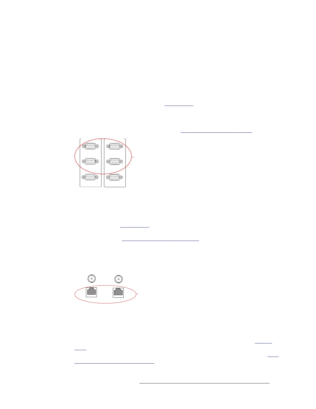
Ethernet Connections
The NV5128 has two Ethernet router control system connections, labeled ‘10/100 BASE T’, as
shown in Figure 2-9. Both connections are shared by both the primary control card and the second-
ary control card. (See Control Cards
on page 21.) Because Ethernet network connections can be
used to connect to alternate control systems, there are no separate connections provided. For instal-
lation instructions, see Ethernet Router Control Connections
on page 61.
In order for the router to communicate with the router control system through an Ethernet connec-
tion, an IP address for the router needs to be set in the control card. The IP address is set using Uni-
Config. For more information, see the UniConfig User’s Guide.
Figure 2-9. Ethernet Connections to Router Control System (Rear View)
GSC Node Bus Connections
Some third-party router control systems require a GSC Node Bus connection. The NV5128 has one
GSC Node Bus connection, labeled ‘NODE BUS’, as shown in Figure 2-10, next page. The con-
nection is shared by both the primary control card and the secondary control card. (See Control
Cards on page 21.) To use the GSC Node Bus connection, an optional module must be installed on
each control card being used. For details, contact NVISION. For installation instructions, see GSC
Node Bus Router Control Connections on page 61.
CTRL 1
CTRL 2
PRI CTRL
DIAG
Serial Connections
to Control System
CTRL 1
CTRL 2
SEC CTRL
DIAG
Ethernet
Connections
to Control
System
10 BASE 2
10/100 BASE T
10 BASE 2
10/100 BASE T
COMMON
TO
PRI & SEC