28 Rev 2.3 • 14 Oct 08
2. Introduction
Active Cards
Output Card
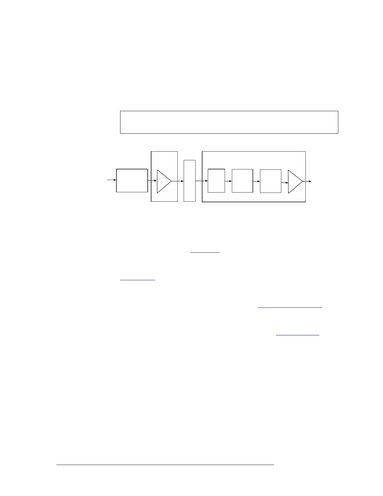
The SD output card (EM0384) receives up to 16 SD signals from the motherboard. A bus receiver
feeds the signals to a crosspoint array (128 inputs x 16 outputs) for switching. From the crosspoint,
the SD signal is forwarded to a re-clocker, which automatically switches between 143, 177, and
270
Mb/s sample rates. If the sample rate is non-standard, the re-clockers pass the signal to the
cable driver, which forwards the signal to passive backplane I/O connectors for distribution.
Figure 2-21 shows the SD signal path.
Figure 2-21. SD Digital Video Signal Flow
Classic SWB
The Classic SWB input card set (EM0395) is composed of two cards and occupies two slots in the
router. The backplanes housing I/O connectors for receiving and distributing SWB signals are
active and unique to video signals. (See Backplanes
on page 13.) There are two types of back-
planes: one for inputs (EM0396) and one for outputs (EM0424).
There is a jumper that configures the Classic SWB card set for DVB/ASI operation. For more infor-
mation, see Configuration
on page 67.
A single Classic SWB card set can switch 16 inputs x 16 outputs. Two card sets can be linked
together such that the inputs from each card set is sent to the other card set, to create a switching
configuration of 32 inputs x 32 outputs. For more information, see Switching Configurations
on
page 8.
Up to 16 incoming signals are received through connectors on an associated I/O backplane. Equal-
izers on the backplane automatically compensate for length of cable. (See Technical Details
on
page 83.) The equalized signal is forwarded to the card set and a crosspoint array (32 inputs x 16
outputs) for switching. From the crosspoint, the SWB signal is forwarded to a re-clocker, which
automatically switches between 143, 177, 270, 360, and 540
Mb/s, and 1.483 and 1.485 Gb/s sample
rates. If the sample rate is non-standard, the re-clockers pass the signal to the backplane for distri-
bution without attempting to re-clock it. The signal is then sent to a cable driver on the backplane,
which forwards the signal to backplane I/O connectors for distribution.
Note If desired, each re-clocker can be selectively disabled or re-enabled using UniCon-
fig. See the UniConfig User’s Guide.
I/O
Connectors
(up to 16)
Motherboard
Input Card
Cable
Equalizers
on backplane
Recr
Output Card
XPT
128x16
I/O
Connectors
(up to 16)
Re-
clocker