14 Rev 2.3 • 14 Oct 08
2. Introduction
Module Slots and Rear Connectors
Machine Control Breakout Panel
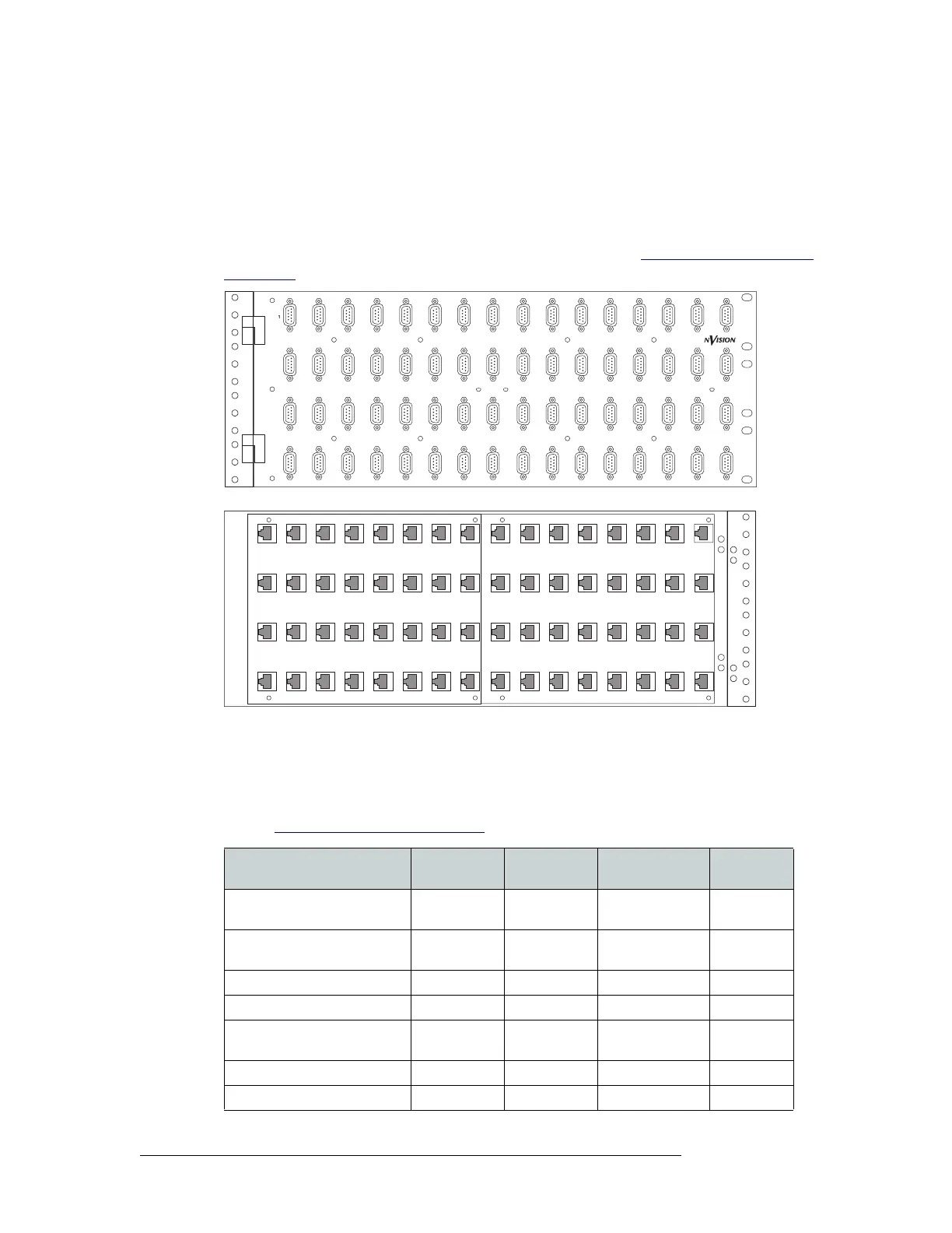
The backplane module for machine control signals has 16 RJ-45 connectors. NVISION offers an
optional machine control breakout panel (BP2-PORT-64) that can be used with up four machine
control backplane modules. The panel has 64 RJ-45 connectors on one side and 64 DE9 (female)
connectors on the other, as shown in Figure 2-6. The DE9 connector wiring follows SMPTE-
defined pin assignment standards. For installation instructions, see Installing Machine Control
Backplanes on page 42.
Figure 2-6. Optional Machine Control Breakout Panel
Backplane Types and Signals
The following is a list of each backplane type, associated connectors, signal types managed, and the
number of signals each backplane can receive or distribute. For the part number for each backplane
list, see Cards, Card Sets, and Backplanes
on page 93.
MACHINE CONTROL
BREAKOUT PANEL
BP-PORT-64
2345678 910111213
14 15 16
17 18 19 20 21 22 23 24 25 26 27 28 29
33 34 35 36 37 38 39 40 41 42 43 44 45
49 50 51 52 53 54 55 56 57 58 59 60 61
30 31 32
46 47 48
62 63 64
Front View
Rear View
Signal Types
Backplane
Name
Connector
Type
Connectors per
Backplane
Signals
Managed
AES unbalanced, synchronous AES BNC 16 16 stereo or
32 mono
AES balanced, synchronous AES/TC Phoenix 16 16 stereo or
32 mono
AES unbalanced, asynchronous AES BNC 16 16 stereo
AES balanced, asynchronous AES/TC Phoenix 16 16 stereo
Analog audio Analog audio DB25 4 16 stereo or
32 mono
Digital Video, SD SDI BNC 16 16
Digital Video, SWB SWB BNC 16 16