46 Rev 2.3 • 14 Oct 08
3. Installation
Installing Active Cards
When installing four or fewer standard SWB input cards, it is recommended that the cards be
installed in the right-hand input slots in the frame, beginning with slot 12 and working backwards.
This leaves room for installation of the standard SWB output cards. If your switching configuration
requires 64 SWB outputs or fewer, install the standard SWB main output card (EM0463) in slot 13.
Use slots 14, 15, and 16 for additional standard SWB expansion output cards (EM0465). If more
than 64 outputs are desired, begin by installing input cards and output cards on the left side of the
router frame, when facing the front of the router, beginning with the first slots. (See Figure 2-3 on
page 11.) For more information on switching configurations, see Switching Configurations
on page
8.
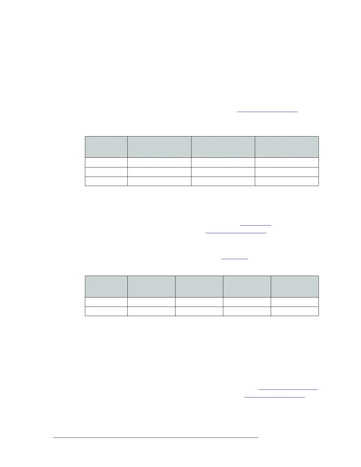
The following lists examples of different configurations using standard SWB cards:
Rules for Classic SWB Card Sets
Classic SWB card sets (EM0395) occupy two slots each. One card set serves as a SWB video
16×16 output crosspoint array. Two classic SWB card sets can be combined to create a 32×32 out-
put crosspoint array. For more information on card functions, see Classic SWB
on page 28. For
more information on switching configurations, see Switching Configurations
on page 8.
Each Classic SWB card set requires two backplanes: One is a 16-input active backplane; it includes
automatic cable equalization circuits for the 16 inputs. The other is an output backplane with active
line drivers for the 16 outputs. For more information, see Backplanes
on page 13.
Classic SWB card set must be installed in specific slots, as follows:
See Figure 2-3 on page 11.
Rules for Machine Control Card Sets
A single machine control card set (EM0482) can be installed in any two adjacent slots to create a
32-port array. However, NVISION recommends that the first 32-port card set and backplane set be
installed in slot 11 and slot 12. If two Machine Control card sets are being combined, to create a 64-
port configuration, the card sets must be installed in slots 11 and 12 and in slots 13 and 14, respec-
tively. (See Figure 2-3 on page 11.) It is not possible to install two independent 32-port module sets
in separate 32-port partitions. For more information on card functions, see Machine Control Signals
on page 32. For more information on switching configurations, see Switching Configurations
on
page 8.
Configuration
Slots for Standard SWB
Input Card (EM0466)
Main Slots for Standard
SWB Output Card
(EM0463)
Expansion Slots for
Standard SWB Output
Card (EM0465)
32 × 48 11, 12 13 14, 15
64 × 64 9, 10, 11, 12 13 14, 15, 16
96 × 96 4, 5, 6, 7, 8, 9 1, 13 2, 3. 4, 14
Configuration
Slots for Classic
SWB Card Set 1
(EM0395)
Slots for Classic
SWB Card Set 2
(EM0395)
Slots for Input
Backplane Slot
Number (EM0396)
Slots for Output
Backplane Slot
Number (EM0424)
16 × 16 Slots 12 and 13 Not used Slot 12 Slot 13
32 × 32 Slots 11 and 12 Slots 13 and 14 Slots 11 and 13 Slots 12 and 14