NV5128 Multi-Format Router • User’s Guide 11
2. Introduction
Module Slots and Rear Connectors
Each slot supports 16 channels, as follows:
• Slots 1 through 4 (for outputs): Slot 1 switches output channels 1 to 16, slot 2 switches output
channels 17-32, and so on.
• Slots 5 through 12 (for inputs) receives and process inputs 1to 128 respectively, in groups of 16
channels per slot, in ascending order, left to right, viewed from the front of the frame.
• Slots 13 through 16 (for outputs) are similar in function to slots 1 to 4, except that the output
channels are in reverse order. That is, slot 13 switches output channels 113 to 128, slot 14
switches 97 to 112, slot 15 switches 81 to 96 and slot 16 switches 65 to 80. The reverse order of
the output channels in the right-hand side of the frame is intentional; it makes it easier to obtain
equal path lengths on the frame’s motherboard, facilitates analog video timing, and facilitates
the use of Classic SWB card sets and machine control card sets installed in slots 11 to 14 (see
Installing Active Cards
on page 44).
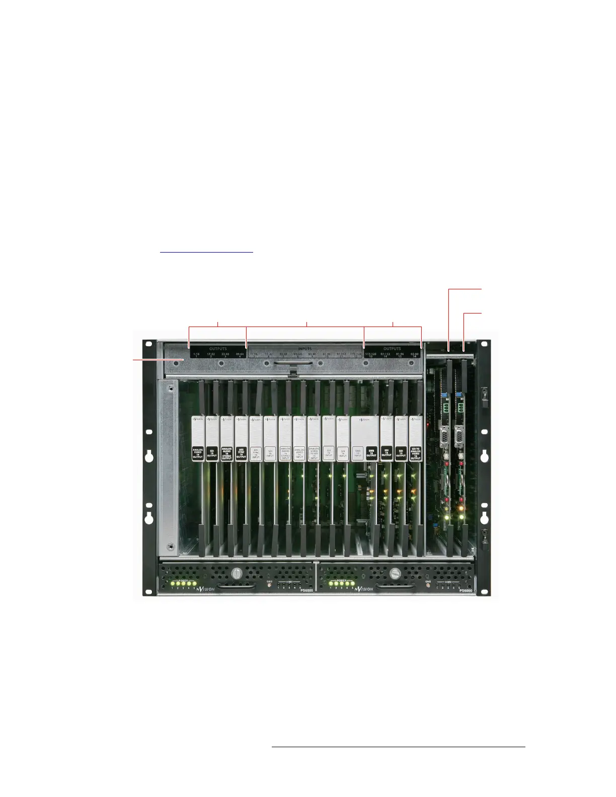
Figure 2-3 shows the location of the input card, output cards, and control card slots, as viewed from
the front.
Figure 2-3. NV5128 Frame with Modules (Front View)
Slots 1–4
(Outputs 1–64)
Slots 5–12
(Inputs 1–128)
Slots 13–16
(Outputs 128–65)
Primary
Control Card
econ
ary
Control Card
Pullout
Fan Tray
Main PS6000 Power Supply Redundant PS6000 Power Supply
 Loading...