70 Rev 2.3 • 14 Oct 08
4. Configuration
Setting Jumpers and Switches on Cards and Card Sets
the card globally. The ‘ON’ position activates mute control; the ‘OFF’ position deactivates mute
control.
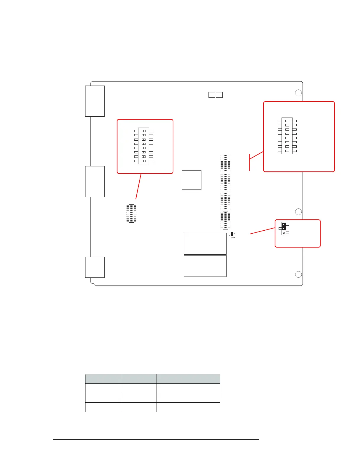
Figure 4-1 shows the location of the DIP switches for the analog audio input card (EM0585).
Figure 4-1. Analog Audio Input Card Switch and Jumper Locations
Operating Levels
Both the analog input card (EM0585) and the analog output card (EM0586) have an additional DIP
switch set that can be used to match the operating level of the facility. For example, if the incoming
signal operating level is +24 dbu, the card can be set to +24 dbu. By matching the incoming signal
level, there is less degradation of the signal when it is converted to digital for internal routing in the
router. Operating levels can be set for +15
dBu, +18 dBu or +24 dBu.
The DIP is SW4 on the input card and S1 on the output card. Only the first two switches on the DIP
are used for the operating level. The following shows the switch positions for each operating level:
By default, all switches are set to ‘OFF’ and the operating level set to +24
dBu.
SW4
NV5128 ANALOG AUDIO 16 STEREO INPUT
NVISION
PC0639-00
EM0585-
R
R
R
R
L
L
L
L
L
L
L
L
R
R
R
R
5
5
6
6
7
7
8
8
9
9
10
10
11
11
12
12
R
R
R
R
L
L
L
L
13
13
14
14
15
15
16
16
SW2
SW3
SW5
DIAGNOSTIC
1
2
3
4
5
6
7
8
OFF
ON
INPUT CHANNEL GAIN
OdB
+6dB
L
L
L
L
R
R
R
1
1
2
2
3
3
4
4
R
SW1
OFF
ON
J21
OFF
ON
J21
Mute Control
INPUT CHANNEL GAIN
OdB
+6dB
L
L
L
L
R
R
R
1
1
2
2
3
3
4
4
R
SW1
Input Gain Control
DIAGNOSTIC
1
2
3
4
5
6
7
8
OFF
ON
Operating Level
SW2, SW3, SW5 similar
Switch 1 Switch 2 Operating Level (Max)
Off — +24 dBu
On Off +18 dBu
On On +15 dBu