64 Rev 2.3 • 14 Oct 08
3. Installation
Making Alarm Connections
The DE9 connector can be set for RS-422, but adjustments will need to be made in UniConfig.
For more information, see the UniConfig User’s Guide. The following lists the wiring for the
DE9 pin connectors for RS-422:
3 Connect the other end of the cable to the hardware running the UniConfig application.
4 If a secondary control card is installed (optional for redundancy), connect to the ‘DIAG’ con-
nection in the ‘SEC CTRL’ section using a DE9 connector and a serial cable as described in
Step 2 and Step 3.
Making Alarm Connections
The NV5128 provides alarms that send notification when a system malfunction occurs, such as
when a fan or power supply is not functioning properly. Alarms can be connected to an external
alarm indicator that displays visual cues when an alarm is activated. NVISION does not provide
external indicator equipment, but does provide instructions on wiring the alarm connections. See e
Alarm Indicator Equipment
on page 64. The router also sends status information to the router con-
trol system. For a detailed description of the router alarm connection, see Making Alarm Connec-
tions on page 64.
How to make alarm connections
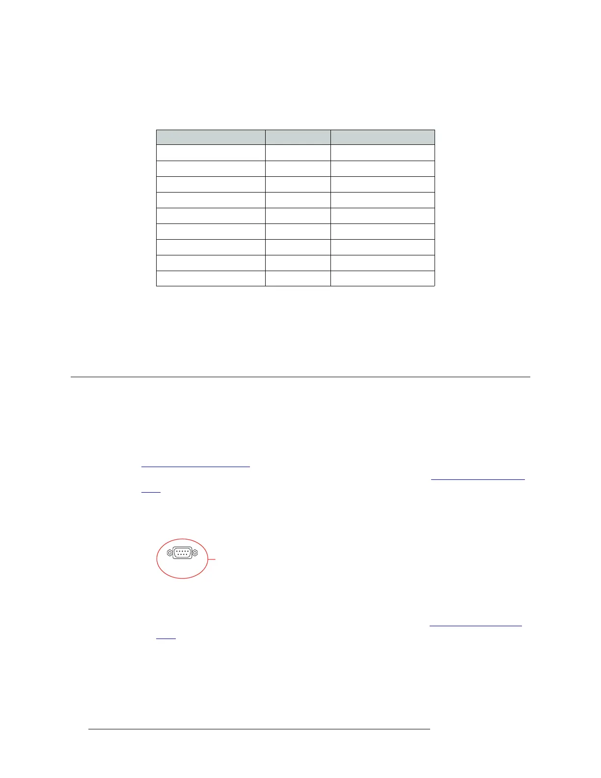
1 On the rear of the router, locate the ‘ALARMS’ connection, as shown in Figure 3-17.
Figure 3-17. Alarms Connection (Rear View)
2 Connect to the ‘ALARMS’ connection using a DE9 connector and serial cable.
3 Connect the other end of the cable to an external alarm indicator. See Alarm Indicator Equip-
ment, following, for information on wiring the DE9 connector.
Alarm Indicator Equipment
An external alarm indicator can be created to display visual cues when a failure has occurred on the
router frame. The ‘ALARM’ connection on the rear of the NV5128 uses a DE9 connector. LEDs
Hardware Pins Router
Ground 1 ------------1 Ground
Rx– 2 ------------2 Tx–
Tx+ 3 ------------3 Rx+
Transmit Common 4 ------------4 Receive Common
N/C 5 ------------5 N/C
Receive Common 6 ------------6 Transmit Common
Rx+ 7 ------------7 Tx+
Tx– 8 ------------8 Rx–
Ground 9 ------------9 Ground
ALARMS
System Alarm
Connection