60 Rev 2.3 • 14 Oct 08
3. Installation
Making Router Control System Connections
How to make a serial connection to the router control system
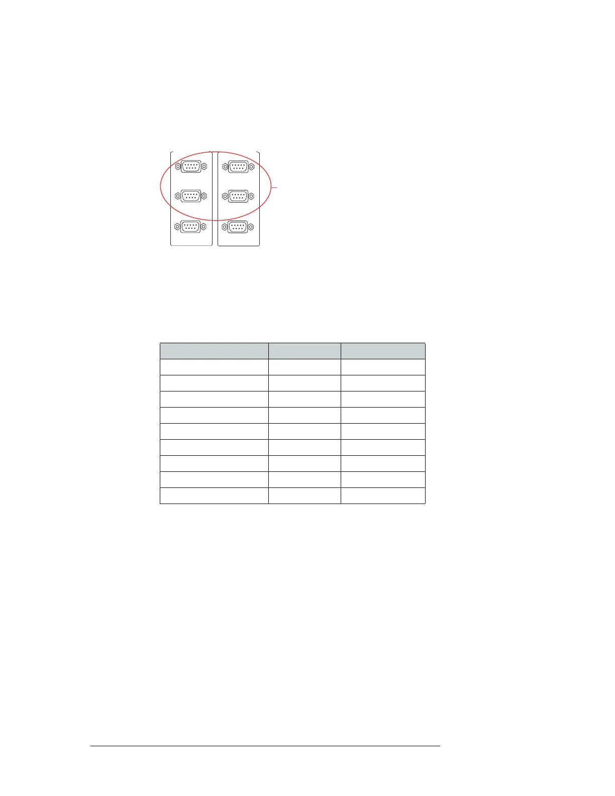
1 Locate the serial control connections on the rear of the router, as shown in Figure 3-13. Serial
control connections are labeled ‘PRI CTRL’ for the primary control card and ‘SEC CTRL’ for
the secondary control card.
Figure 3-13. Serial Connections to Router Control System (Rear View)
2 Connect to the ‘CTRL 1’ connection in the ‘PRI CTRL’ section using a DE9 connector and
serial cable.
3 Connect the other end of the serial cable to the (primary) router control system using a DE9
connector.
The following lists the pin wiring for the DE9 connector:
4 If a secondary control card (optional for redundancy) is installed, connect to the ‘CTRL 1’ con-
nection in the ‘SEC CTRL’ section as described in Step 2 and Step 3.
5 If an alternate router control system (e.g., for redundancy or dual control) is being used, make
connections as follows:
a Connect to the ‘CTRL 2’ connection in the ‘PRI CTRL’ section using a DE9 connector and
serial cable.
b Connect the other end of the serial cable to the secondary router control system using a DE9
connector, wiring the connector as described in Step 3.
c Connect to the ‘CTRL 2’ connection in the ‘SEC CTRL’ section using a DE9 connector and
serial cable.
d Connect the other end of the serial cable to the secondary router control system using a DE9
connector, wiring the connector as described in Step 3.
CTRL 1
CTRL 2
PRI CTRL
DIAG
Serial Connections
to Control System
CTRL 1
CTRL 2
SEC CTRL
DIAG
Router Control System Pins Router
Ground 1 ------------1 Ground
Rx– 2 ------------2 Tx–
Tx+ 3 ------------3 Rx+
Tx Common 4 ------------4 Rx Common
N/C 5 ------------5 N/C
Rx Common 6 ------------6 Tx Common
Rx+ 7 ------------7 Tx+
Tx– 8 ------------8 Rx–
Ground 9 ------------9 Ground