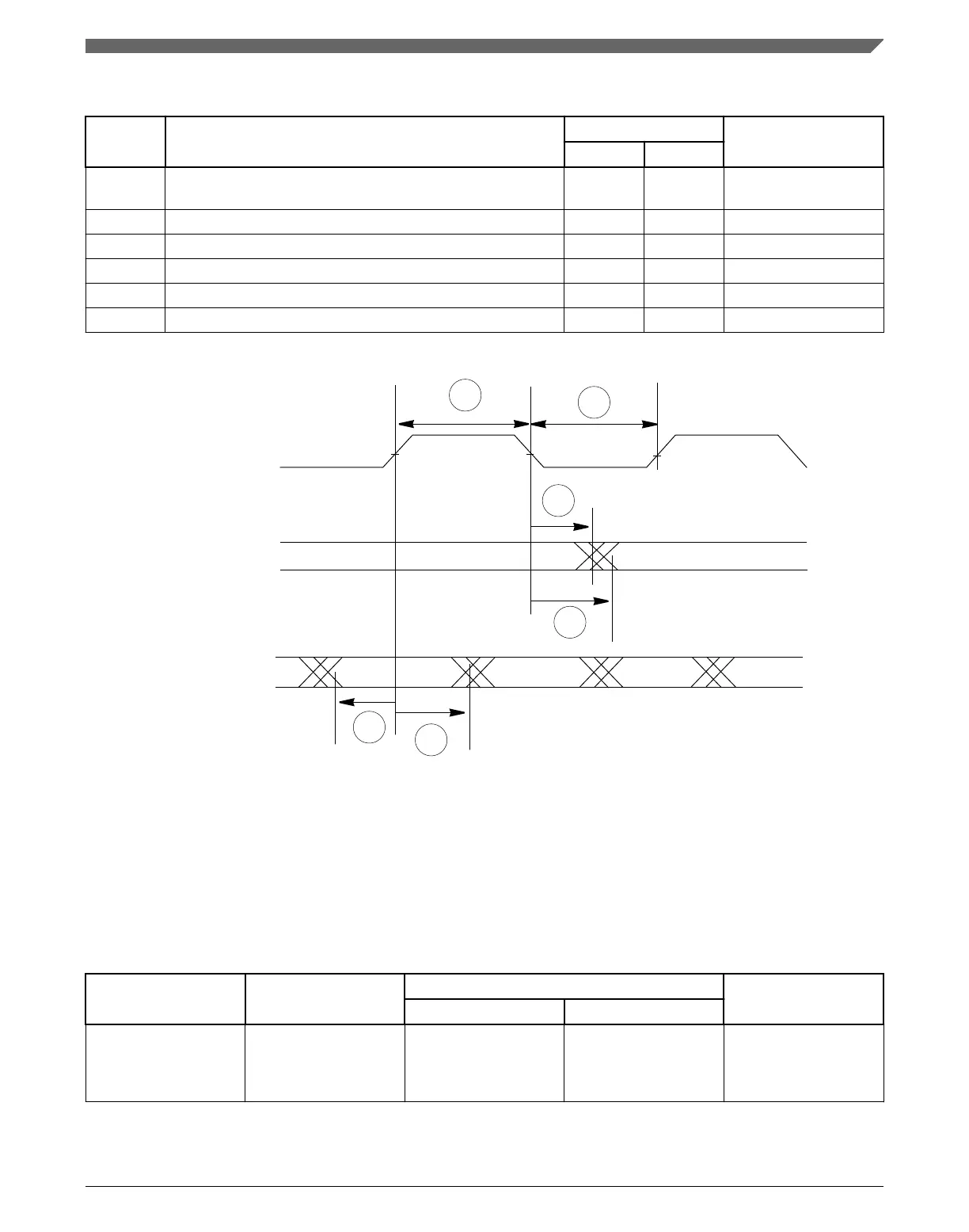
Table 49. MII-lite serial management channel timing
Spec Characteristic
Value Unit
Min Max
M10 MDC falling edge to MDIO output invalid (minimum
propagation delay)
0 — ns
M11 MDC falling edge to MDIO output valid (max prop delay) — 25 ns
M12 MDIO (input) to MDC rising edge setup 10 — ns
M13 MDIO (input) to MDC rising edge hold 0 — ns
M14 MDC pulse width high 40% 60% MDC period
M15 MDC pulse width low 40% 60% MDC period
M11
M10
MDC (output)
MDIO (output)
M12
M13
MDIO (input)
M14
M15
Figure 44. MII-lite serial management channel timing diagram
18.3.5
RMII serial management channel timing (MDIO and MDC)
The FEC functions correctly with a maximum MDC frequency of 2.5 MHz.
Table 50. RMII serial management channel timing
Spec Characteristic
Value Unit
Min Max
M10 MDC falling edge to
MDIO output invalid
(minimum propagation
delay)
0 — ns
Table continues on the next page...
AC specifications
SPC5746R Microcontroller Data Sheet, Rev. 6, 06/2017
NXP Semiconductors 83

 Loading...


