NXP Semiconductors
AN13134
PN76 family evaluation board quick start guide
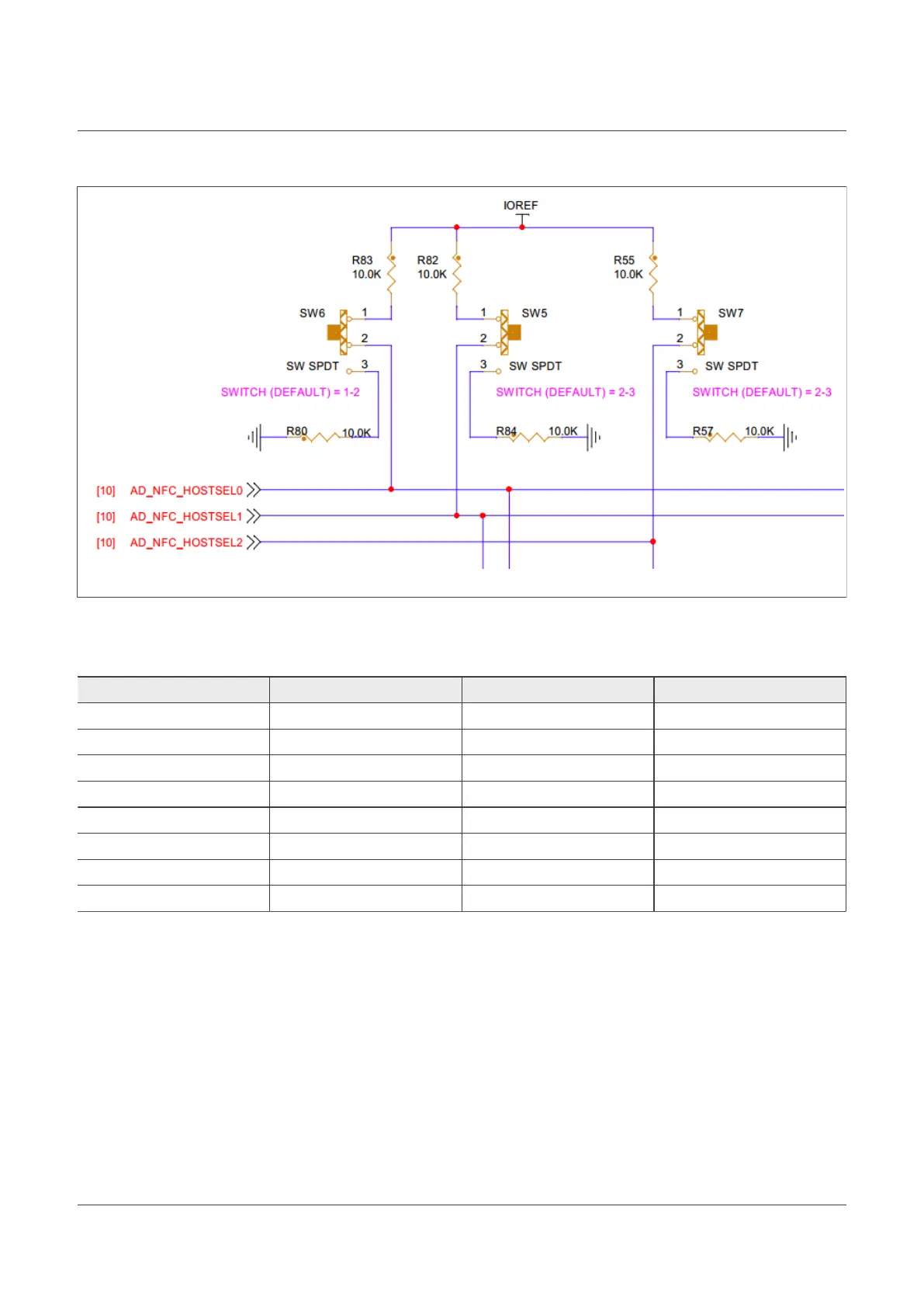
Figure 13. PNEV7642A HIF selection switches schematic
Following table defines the chosen host-interface. Where the value "0" represents a Low signal (GND) and "1" a
high signal ("IOREF").
Interface HOSTSEL2 (SW7) HOSTSEL1 (SW5) HOSTSEL0 (SW6)
I2C 0 0 0
SPI (default) 0 0 1
UART 0 1 0
I3C 0 1 1
USB 1 0 0
SPI 1 0 1
USB 1 1 0
USB 1 1 1
Table 8. PNEV7642A HIF selection
Note: There are multiple options for USB. It does not matter which one is taken. Ultimately the signal to the
controller is the same.
2.1.4.2 IOREF
Per default, IOREF is not connected and this represents the "standalone mode" of the board (no Arduino
controller installed - like our LPC55S16 board).
• Standalone: Not populated
• Follower: Populated on 1-2
– This is the case, if a host is installed. E.g., using the LPC55S16 as host.
• Leader: Populated on 2-3
– In case you have an arduino shield on top. Like the TDAEV8035 board.
AN13134 All information provided in this document is subject to legal disclaimers. © 2023 NXP B.V. All rights reserved.
Application note Rev. 2.5 — 2 May 2023
15 / 57

 Loading...


