NXP Semiconductors
AN13134
PN76 family evaluation board quick start guide
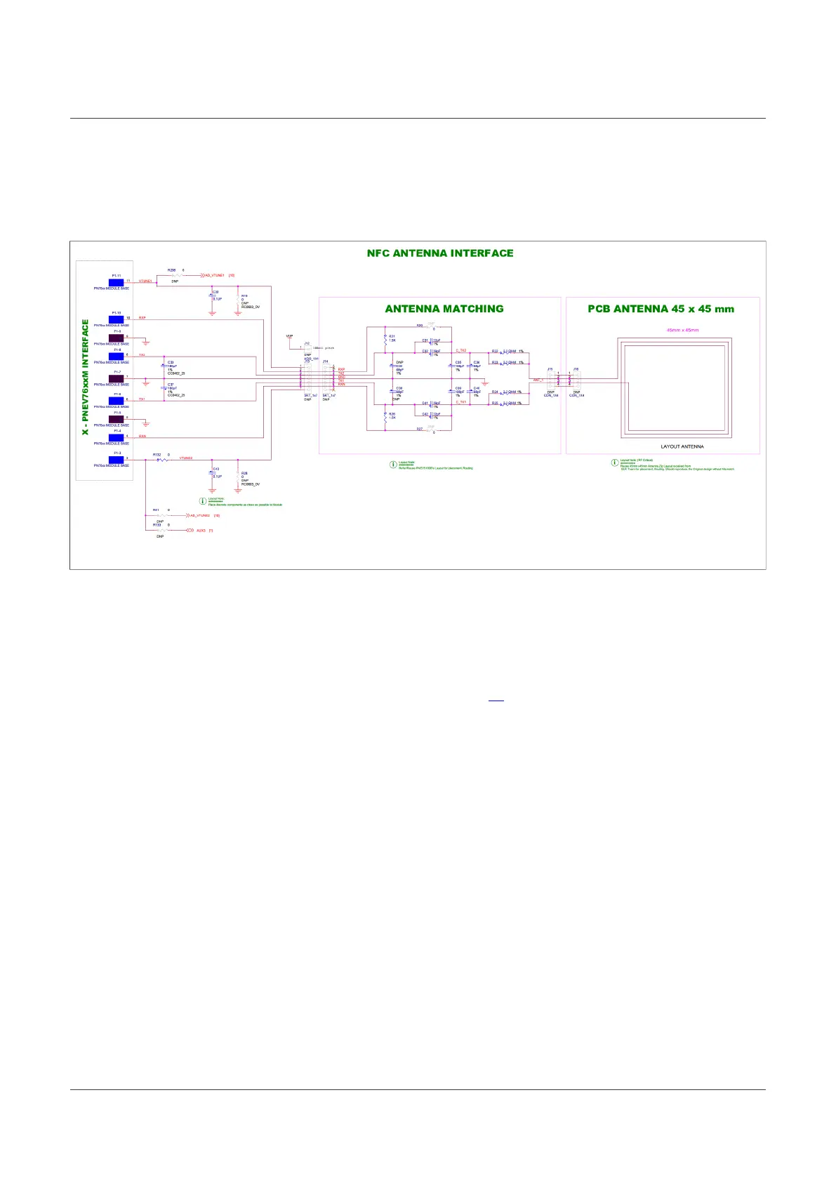
2.1.3 Antenna
The antenna connection uses the standard tuning circuit. The EMC filter is designed with a cut-off frequency of
fEMC = 14.25 MHz, and the antenna impedance is tuned to Z = 15…16Ω.
Figure 12. Antenna schematic
2.1.4 Jumper settings
The development board is hosting many jumpers and switches. This is to enable the configuration of every
signal and easier debugging. With the downside of looking, and being, more complex.
The following chapters describe the most important jumpers for your daily debugging. For more information
about other jumpers, consolidate the schematics of the base board [2].
2.1.4.1 Host interface selection
On this board, the HIF (host interface) can be chosen by three red switches. Those act either as pullup or
pulldown with 10 kOhm toward the signal IOREF or GND.
The switches are not grouped together but spread over the board (SW7 near power jack, SW5 and SW6 near
OpenSDA).
AN13134 All information provided in this document is subject to legal disclaimers. © 2023 NXP B.V. All rights reserved.
Application note Rev. 2.5 — 2 May 2023
14 / 57

 Loading...


