EnForcer™ SCR Service Manual I.B. 1561
5
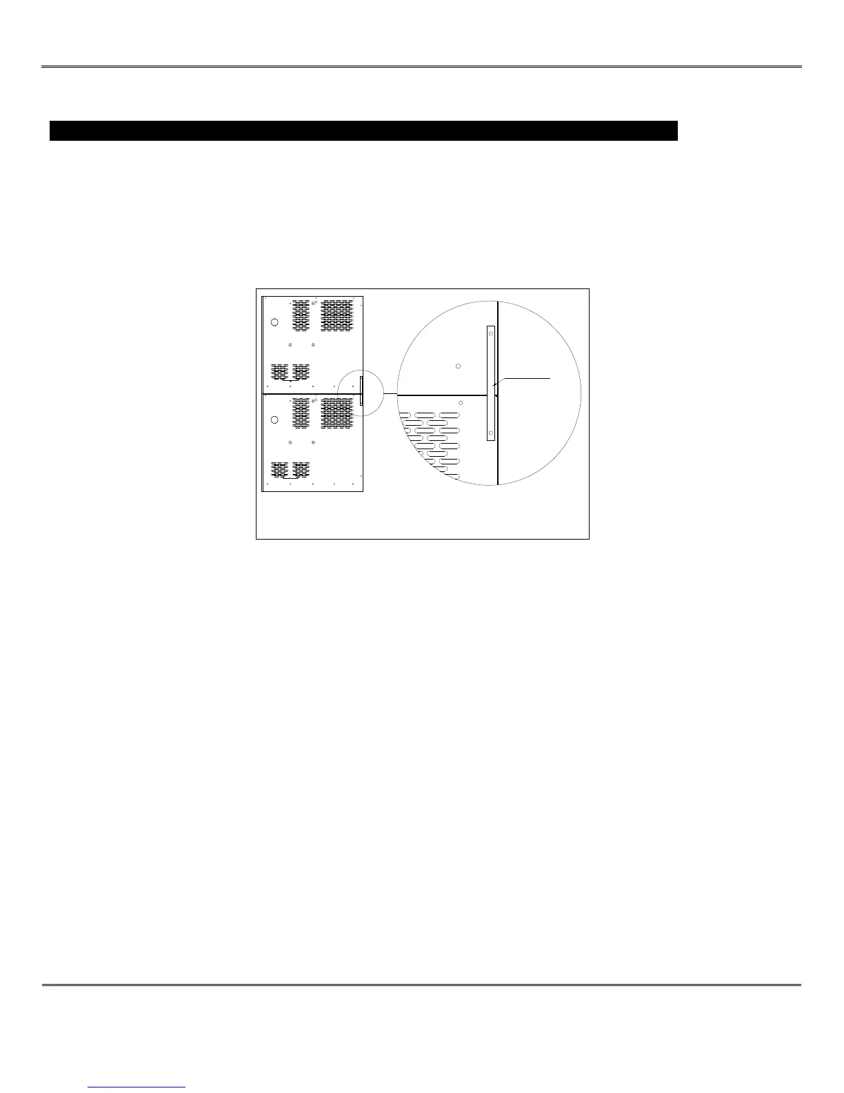
TWO STACKED CHARGERS, RIGHT SIDE VIEW
METAL STRAP
INSTALLATION
WARNING: The shipping pallet must be removed for proper and safe operation.
LOCATION
For maximum trouble-free service, choose a location that is free of excess moisture, dust, and corrosive fumes. Also,
avoid locations where temperatures are high or where liquids will drip on the charger. Allow six (6) inches of clearance at
rear and sides of the charger for air circulation. Do not obstruct the ventilating openings or the space under the charger.
STACKING MULTIPLE CHARGERS
These chargers can be stacked up to a maximum of 3 units high. Chargers are not designed to be stacked side by side
due to ventilation requirements.
1) Position the first charger so that a minimum of 6 inches of space is between the charger and any wall, and 12
inches between the charger and any other equipment.
2) Place the second charger on top of the first. Align the bolt holes on each charger.
3) Fasten both charger cabinets together securely using 3/8” bolts and nuts.
NOTE: The two bolts toward the back of the charger may be omitted if an after market metal strap)(about 8
inches) is used to secure both chargers. Remove existing ¼” screws of the charger sides and attach strap with
screws. Refer to picture.
Hardware kit #X225-99-0-2 can be ordered to attach two chargers.
4) Repeat steps 2 and 3 for the third charger.
5) Stacked chargers must be fastened to the wall using devices suitable for the wall construction and the bolt holes
at the top of the highest charger.
NOTE: Ambient temperature at all levels cannot exceed 104°F/40°C.
ELECTRICAL CONNECTIONS
To prevent failure of the charger, be sure it is connected to the correct line voltage.
ON THREE PHASE UNITS
Connect all the chargers as follows:
Phase A to L1 (fuse block)
Phase B to L2 (fuse block)
Phase C to L3 (fuse block)