The Ultimate Ice Resurfacer 41
5.4 Ice Making Water Control Panel Optional
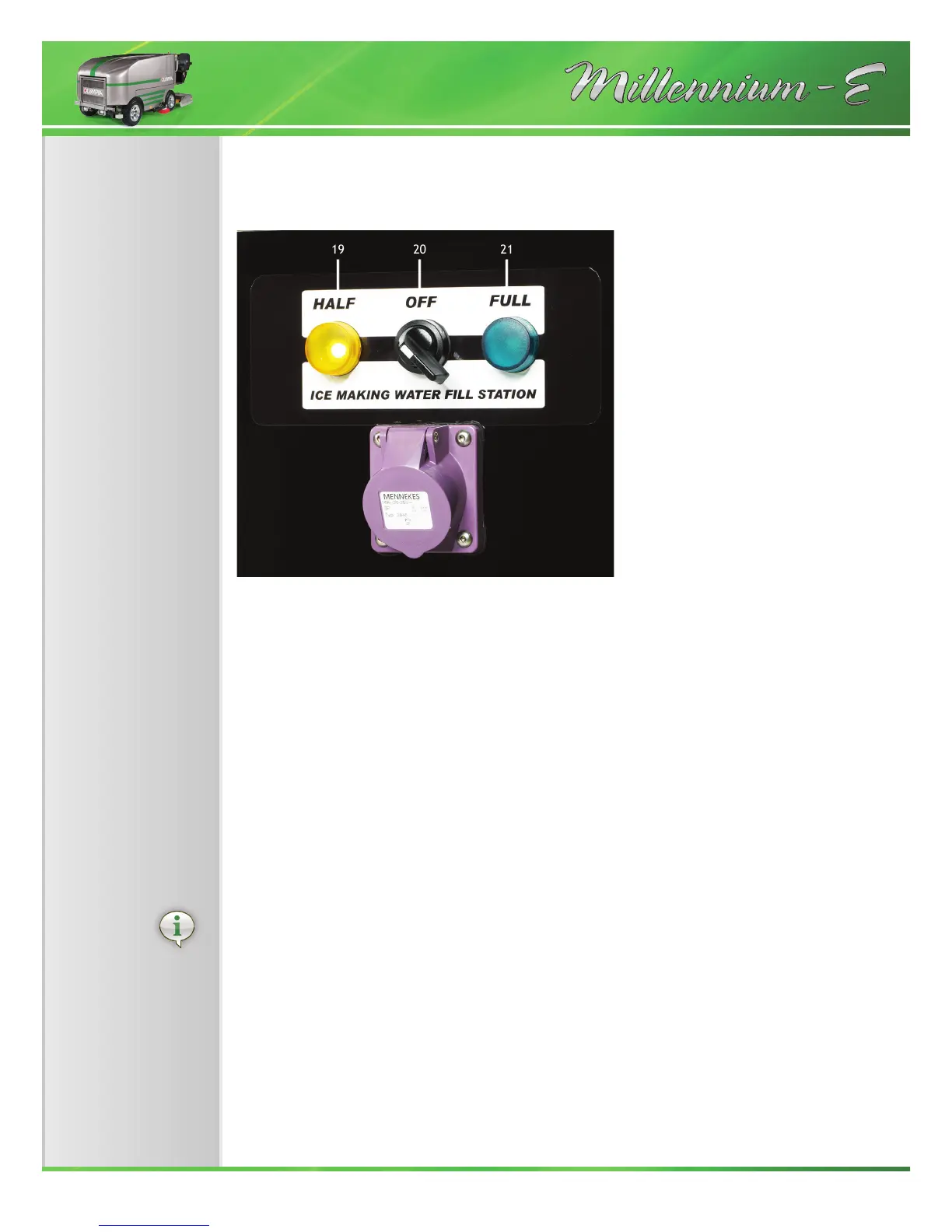
Fig. 5.4: Ice Making Water control panel
Item 19 Indicator lamp for water tank level HALF FULL
Item 20 Selector switch
Item 21 Indicator lamp for water tank level FULL
This panel controls how much hot water can be put into the ice resurfacer.
The ice resurfacer is supplied with an electric water valve, to be mounted onto the water
supply line in the building. Power for this valve is supplied from the ice resurfacer. Once
mounted and wired.
The water hose down stream from the solenoid valve should not be too big in relation to the
water pressure and pipe size, because a pressure dierence of 0,5 bar (7 psi) is needed to
close the solenoid valve.
The solenoid valve plug of the water supply pipe is connected at the Ice Making Water Control
Panel and the water level for the water tank is set there. At the left of the selector switch there
is a yellow indicator lamp (Fig. 5.4, Item 19) for half lling the water tank. At the right there
is a green indicator lamp (Fig. 5.4, Item 21) for completely lling the water tank. To select the
desired ll level, turn the selector switch (Fig. 5.4, Item 20) in the appropriate direction.
19 20 21