U.S.A.
Jabsco
Cape Ann Industrial Park
1 Kondelin Road
Gloucester, MA 01930
Tel: 978.281.0440
Fax: 978.281.6177
UNITED KINGDOM
Jabsco
Bingley Road, Hoddesdon
Hertfordshire EN11 OBU
Tel: +44 (0) 1992 450145
Fax: +44 (0) 1992 467132
CANADA
Fluid Products Canada
55 Royal Road
Guelph, Ontario N1H 1T1
Tel: (519) 821.1900
Fax: (519) 821.2569
JAPAN
NHK Jabsco Company Ltd.
3-21-10, Shin-Yokohama
Kohoku-Ku, Yokohama, 222
Tel: 045.475.8906
Fax: 045.475.8908
GERMANY
Jabsco GmbH
Oststrasse 28
22840 Norderstedt
Tel: +49-40-53 43 73 -0
Fax: +49-40-53 53 73 -11
THE PRODUCTS DESCRIBED HEREIN ARE
SUBJECT TO THE JABSCO ONE YEAR LIMITED
WARRANTY, WHICH IS AVAILABLE FOR YOUR
INSPECTION UPON REQUEST.
© Copyright 2004, ITT Industries Printed in U.S.A. All Rights Reserved Form: 43000-0032 Rev. 12/2004
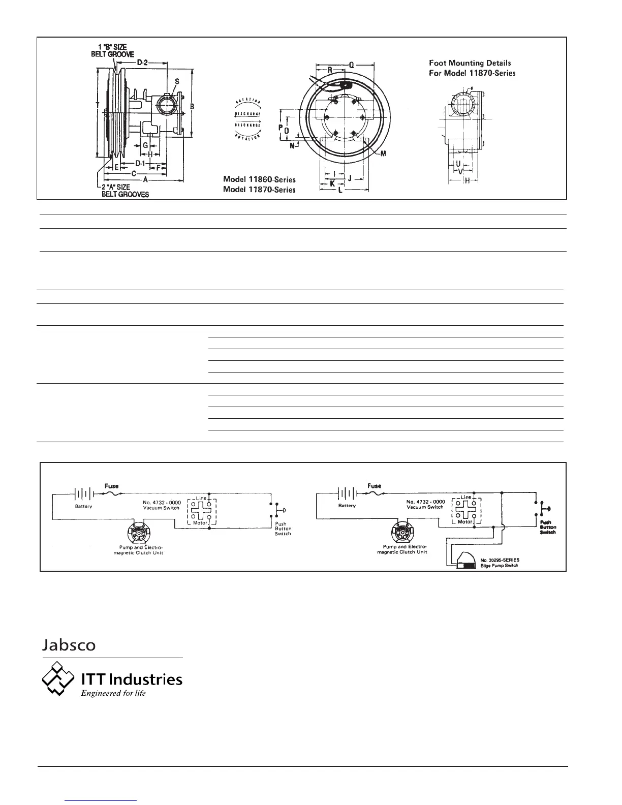
TABULATION OF DIMENSIONS (Inches and Millimeters)
Model A B C D-1 D-2 E F G H I J K L M N O P Q
11860 6-3/16 5-3/8 4-29/32 3-9/16 3-7/8 5/8 1-5/16 3/4 1-1/2 1-9/16 3-1/8 2 4 13/32 1/4 1-7/8 2-1/2 4-3/4
Series 157 137 125 90 98 16 33 19 38 40 79 51 102 10 6 48 64 21
11870 8-3/16 6-1/16 7-1/16 5-1/4 5-9/16 5/8
——
1-7/32 2-5/16 2-1/4 4-1/2 2-3/4 5-1/2 13/32 5/16 2-9/16 3-13/16 5-7/8
Series 208 154 179 133 141 16 31 59 57 114 70 140 10 8 65 97 149
RSTUV
2-3/8 1" 7
————
60 NPT 178
2-15/16 1-1/4" 7 3/16 1-1/2
75 NPT 178 21 38
CAPACITY TABLES
Total Head 500 RPM 1160 RPM 1750 RPM 2450 RPM 3000 RPM
kg per feet of meters of
psi sq cm water water
GPM LPM HP GPM LPM HP GPM LPM HP GPM LPM HP GPM LPM HP
4.3 0.3 10 3.0 6.0 22.7 1/4 14.8 56.0 1/3 23.3 88.2 3/4 32.5 123.0 1 34.8 131.7 1-1/2
11860
8.7 0.6 20 6.1 5.5 20.8 1/4 14.1 53.4 1/2 22.3 84.4 3/4 31.8 120.4 1-1/2 34.2 129.5 1-1/2
Series
17.3 1.2 40 12.2 4.0 15.1 1/4 12.0 45.4 1/2 19.5 73.8 3/4 28.5 107.9 1-1/2 32.5 123.0 2
26.0 1.8 60 18.3 — — — 8.8 33.3 3/4 15.0 56.8 1 23.5 89.0 1-1/2 29.8 112.8 2
34.6 2.4 80 24.4 —————————17.064.41-1/223.890.12
4.3 0.3 10 3.0 18.0 68.1 1/2 41.0 155.2 1 62.0 234.7 1-1/2 ——————
11870
8.7 0.6 20 6.1 17.0 64.4 1/2 40.0 151.4 1 60.0 227.1 1-1/2 ——————
Series
17.3 1.2 40 12.2 14.0 53.0 1/2 37.0 140.1 1-1/2 55.0 208.2 2 ——————
26.0 1.8 60 18.3 — — — 30.0 113.6 1-1/2 50.0 189.3 2 ——————
34.6 2.4 80 24.4 ——————40.0151.43 ——————
WIRING DIAGRAMS
Remote Control Engine Driven Pump
(While engine is running)
Remote Control and Automatic Engine Driven Bilge Pump
(While engine is running)
REMOTE CONTROL: Install a pushbutton switch at one or more
locations (multiple switches should be wIred parallel). Depress
pushbutton for 2 seconds. If there is water in bilge, pump will operate
until dry, at which time vacuum switch will stop pump. If no water is in
bilge, pump will stop when pushbutton is released.
AUTOMATIC BILGE PUMP: Install No. 30295-Series Automatic Bilge
Pump Switch where it will energize clutch at maximum high water level
in bilge. When water raises switch float, pump will start. Vacuum switch
will maintain closed circuit until bilge is pumped dry. Pump will
automatically stop, preventing impeller damage.
DIMENSIONAL DRAWING