8
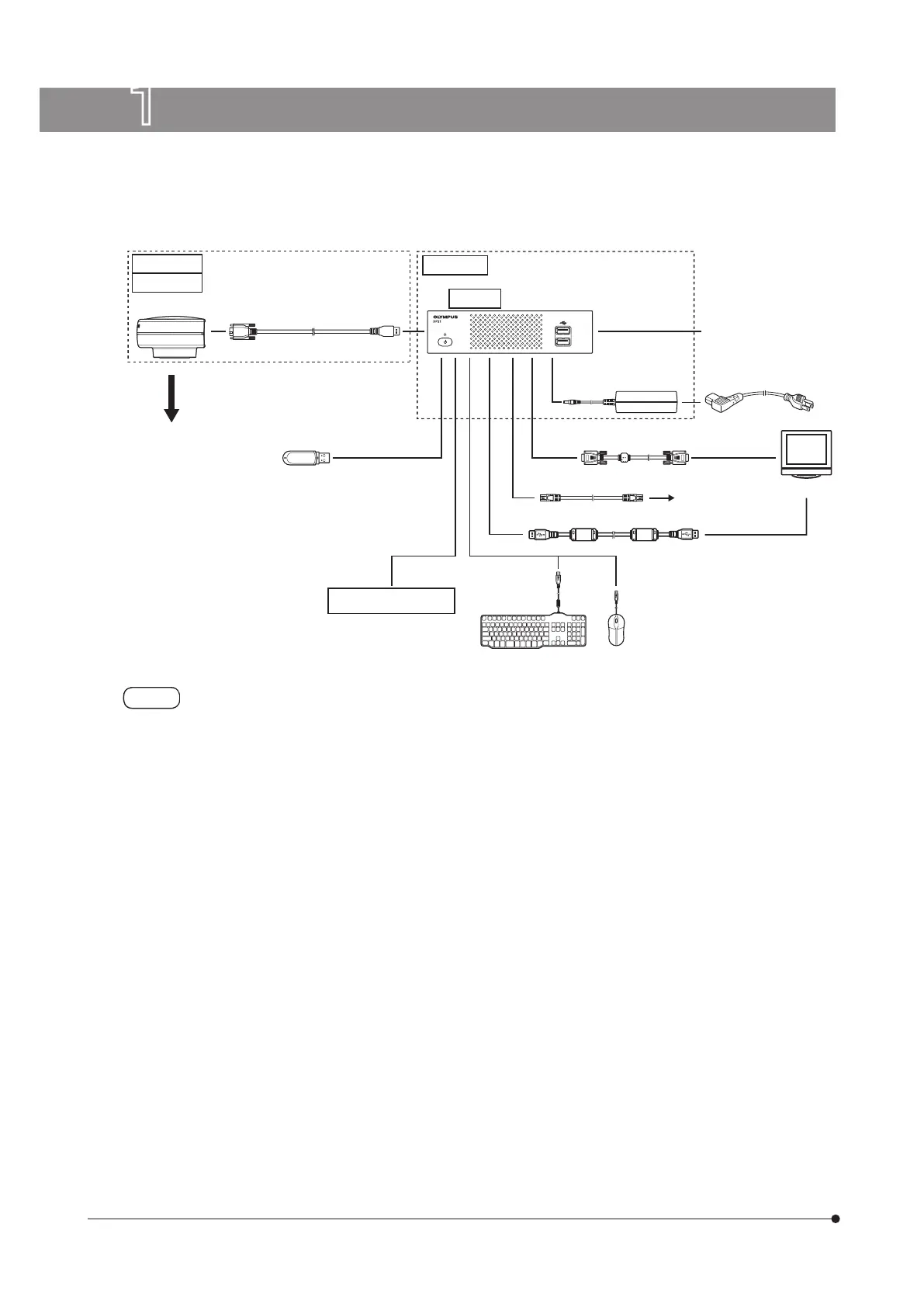
1 System diagram
If the display is connected via a display switcher, a malfunction may be caused. Do not use a display
switcher.
} The image color setup matching the microscope is required for faithful color reproduction. For details, refer to p.34.
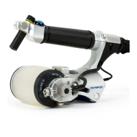
} Consult Olympus for the compatible microscope and camera adapter.
} Do not use the interface cable for the other purpose than intended use.
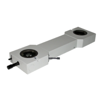
Camera adapter
Interface cable
USB cable for touch panel
USB memory
AC adapter
Control box
Power cord
Display cable
LAN cable
To network
Display
Keyboard
Mouse
DP22-CU
DP27-CU
Camera head
DP2-SAL
D2-CB
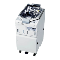
Control box for
microscope system
Other USB devices