90
8-2 Connecting procedures
For procedures to connect the microscope to the control box, refer to the instruction manual of the relevant control box
or microscope.
· Remove only the cover/seal of necessary connectors on the control box.
· Be sure to connect only units specified by Olympus to each connector. If units which are not specified
by Olympus are connected, the full performance is not ensured.
· Use RS232C cable for connecting the control box for microscope and the D2-CB.
· Be sure to turn OFF the main switch of each unit when connecting the cable.
· Align the connector orientation and insert it completely to the end. If the connector has fixing screws,
be sure to fix them.
· Inserting the connectors which are not specified by Olympus may damage them.
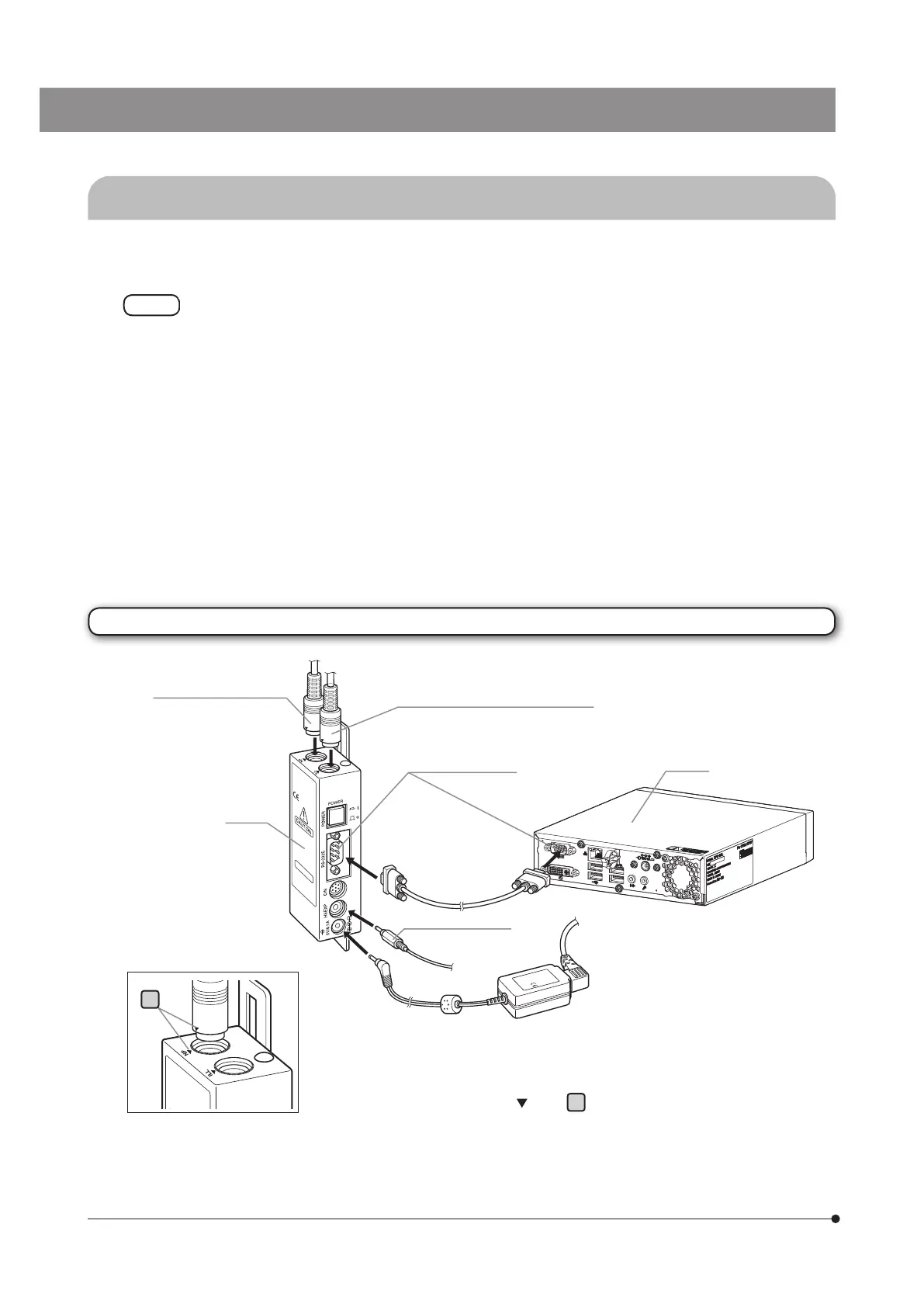
The connecting procedures are described below by using U-CBS as an example. For other connecting procedures, refer
to instruction manuals of devices to be connected.
Connecting to U-CBS
U-CBS
Connector of the coded
revolving nosepiece
D2-CB
RS232C connector
AC adapter for U-CBS
When attaching the connector of the coded revolving nosepiece or the coded
illuminator, insert it by aligning the
mark.
a
U-HSEXP connector
RS232C cable
(provided with U-CBS)
a
Connector of the coded illuminator