M - 2
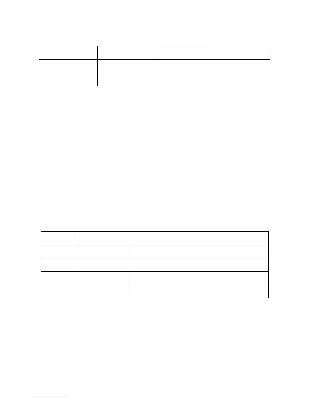
The Modbus Message frame is shown below
DEVICE ADDRESS FUNCTION CODE DATA CRC CHECK
8 BITS
hh
8 BITS
hh
k x 8 BITS
hhh….
16 BITS
hhhh
where:
• h (hex. Number) – character,
• k – integers depend on the contents of the data format.
Device Address Code
• The address message frame contains eight bits. The slave device addresses are
in the range of 1 ... 199 decimal. A master addresses a slave by placing the slave
address in the address field of the message. When the slave sends its response,
it places its own address in this address field of the response to let the master
know which slave is responding.
• Address 0 is used for the write command broadcast that commands all controllers
on network, which all slave devices recognize
4. Function Code
• The function code field of a message frame contains eight bits (RTU). Valid
codes are in the range of 1 ... 255 decimal. Of these, some codes are applicable
for the Universal Input Meters.
• When a message is sent from a master to a slave device the function code field
tells the slave what kind of action to perform.
• The following functions are supported by the Universal Input Meters:
Function
Code
Function Description
03
Read holding
register
Reads the binary contents of holding registers in the
slave
04
Read input
register
Reads the binary contents of input register in the
slave
06
Preset (Write to)
single register
Preset (Write) a value into single holding register
08 Diagnostic
Series of tests for checking communication between
master and slave
• When the slave responds to the master, it uses the function code field to indicate
either a normal (error-free) response or that some kind of error occurred (called
an exception response). For a normal response, the slave simply echoes the
original function code. For an exception response, the slave returns a code that is
equivalent to the original function code with its most significant bit set to a logic 1.

 Loading...


