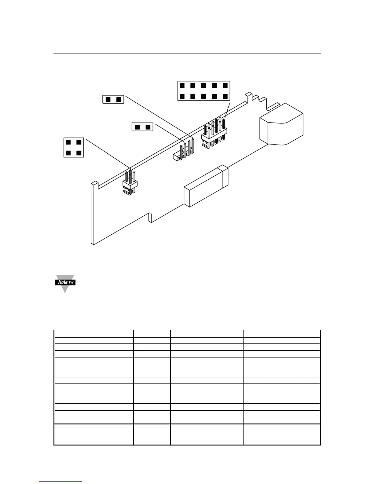
Figure 2-1. RS-232 / RS-485 Option Board
You should install the option board in such a way the pin “1A” of “P11” is
aligned with pin “1A” of “J11” (on main board, refer to Figure 2-2).
When interfacing the meter to devices that do not have handshaking lines, i.e.
RTS/CTS, the S3-E Jumper should be installed. However, when interfacing to a PC,
the S3-E should be removed.
JUMPER RS232 RS485 HALF DUPLEX RS485 FULL DUPLEX
S1-A CLOSE OPEN OPEN
S1-B OPEN CLOSE OPEN
S2-A OPEN CLOSE CLOSE
S3-A
(CLOSE FOR TERMINAL OPEN * *
RESISTOR)
S3-B OPEN CLOSE OPEN
S3-C
(CLOSE FOR TERMINAL OPEN * *
RESISTOR)
S3-D OPEN CLOSE OPEN
S3-E * OPEN OPEN
(CLOSE FOR RTS TRUE)
S4
(CLOSE FOR OPEN * *
CONTINUOUS MODE)
Note: * means optional, select as required.

 Loading...


