171
Timer and Counter Instructions Section 3-5
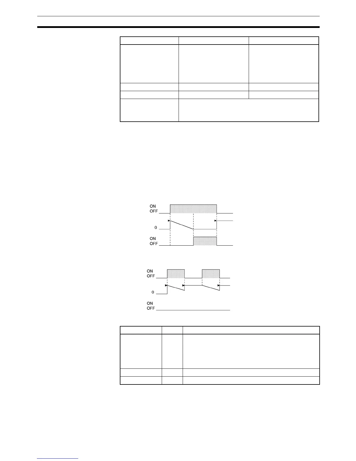
Description When the timer input is OFF, the timer specified by N is reset, i.e., the timer’s
PV is reset to the SV and its Completion Flag is turned OFF.
When the timer input goes from OFF to ON, TIM/TIMX(550) starts decrement-
ing the PV. The PV will continue timing down as long as the timer input
remains ON and the timer’s Completion Flag will be turned ON when the PV
reaches 0000.
The status of the timer’s PV and Completion Flag will be maintained after the
timer times out. To restart the timer, the timer input must be turned OFF and
then ON again or the timer’s PV must be changed to a non-zero value (by
MOV(021), for example).
The following timing chart shows the behavior of the timer’s PV and Comple-
tion Flag when the timer input is turned OFF before the timer times out.
Flags
Constants --- BCD:
#0000 to 9999 (BCD)
“&” cannot be used.
Binary:
&0 to &65535 (decimal)
#0000 to #FFFF (hex)
Data Registers --- DR0 to DR15
Index Registers --- ---
Indirect addressing
using Index Registers
,IR0 to ,IR15
–2048 to +2047 ,IR0 to –2048 to +2047 ,IR15
DR0 to DR15, IR0 to IR15
Area N S
SV
Timer input
Timer PV
Completion
Flag
SV
Timer input
Timer PV
Completion
Flag
Name Label Operation
Error Flag ER ON if N is indirectly addressed through an Index Register
but the address in the Index Register is not the PV
address of a timer.
ON if in BCD mode and S does not contain BCD data.
OFF in all other cases.
Equals Flag = OFF or unchanged
Negative Flag N OFF or unchanged