206
Timer and Counter Instructions Section 3-5
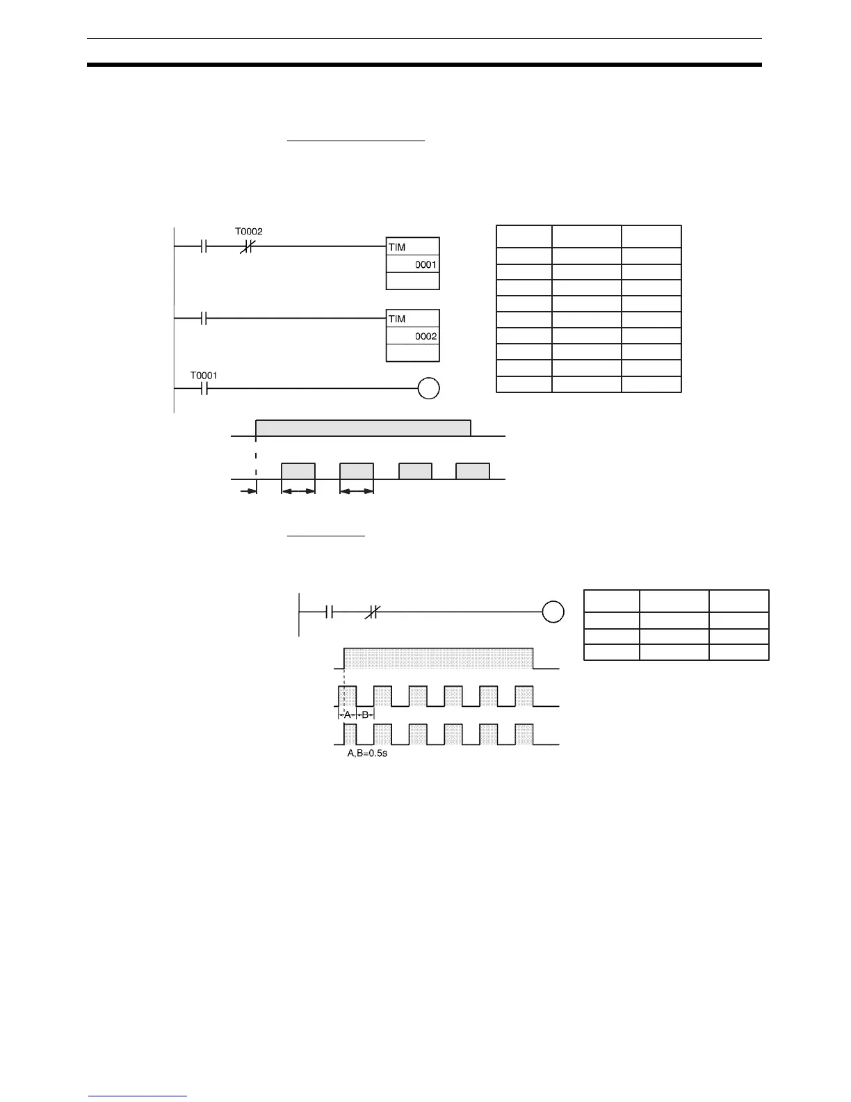
Example 5:
Flicker Bit
The following program examples show two ways to create flicker bits. The
second example just mimics a clock pulse.
Two TIM Instructions
Two TIM timers can be combined to make a bit turn ON and OFF at regular
intervals while the execution condition is ON. In this example, CIO 200.00 will
be OFF for 1.0 second and then ON for 1.5 seconds as long as CIO 0.00 is
ON.
Clock Pulse
The desired execution condition can be combined with a clock pulse to mimic
the clock pulse (0.1 s, 0.2 s, or 1.0 s).
3-5-11 Indirect Addressing of Timer/Counter Numbers
Timer and counter numbers can be indirectly addressed using Index Regis-
ters. When Index Registers will be used for indirect addressing, use
MOVRW(561) (MOVE TIMER/COUNTER PV TO REGISTER) to set the PLC
memory address of the desired timer or counter’s PV to the desired Index
Register.
The following timers and counters can be indirectly addressed using Index
Registers: TIM, TIMX(550), TIMH(015), TIMHX(551), TTIM(087),
TTIMX(555), TMHH(540), TMHHX(552), TIMW(813), TIMWX(816),
TMHW(815), TMHWX(817), CNT, CNTX(546), CNTR(012), CNTRX(548),
CNTW(814), and CNTWX(818). (These are the timers and counters that use
timer and counter numbers.)
CIO 0.00
CIO 200.00
1.5 s1.0 s 1.5 s1.0 s
000000 LD 0.00
000001 AND T0002
000002 TIM 0001
#10
000003 LD 200.00
000004 TIM 0002
#15
000005 LD T0001
000006 OUT 200.00
0.00
200.00
#10
#15
200.00
Instruction OperandsAddress
000000 LD 0.00
000001 AND 1s
000002 OUT 100.00
0.00 P_1 s
100.00
0.00
100.00
Instruction OperandsAddress
1-s clock pulse
1-s clock
pulse