277
Data Shift Instructions Section 3-8
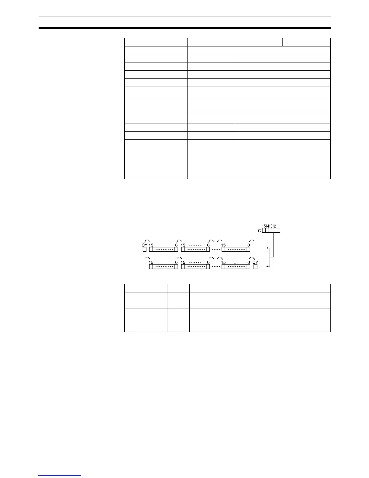
Description When the execution condition of the shift input bit (bit 14 of C) changes to ON,
all the data from St to E is moved in the designated shift direction (designated
by bit 12 of C) by 1 bit, and the ON/OFF status of the data input is placed in
the rightmost or leftmost bit. The bit data shifted out of the shift register is
placed in the Carry Flag (CY).
Flags
Precautions The above shift operations are applicable when the reset bit (bit 15 of C) is set
to OFF.
When reset (bit 15 of C) turns ON all bits in the shift register, from St to E will
be reset (i.e., set to 0).
When St is greater than E, an error will be generated and the Error Flag will
turn ON.
Holding Bit Area H0 to H511
Auxiliary Bit Area A0 to A959 A448 to A959
Timer Area T0000 to T4095
Counter Area C0000 to C4095
DM Area D0 to D32767
Indirect DM addresses
in binary
@ D0 to @ D32767
Indirect DM addresses
in BCD
*D0 to *D32767
Constants ---
Data Registers DR0 to DR15 ---
Index Registers ---
Indirect addressing
using Index Registers
,IR0 to ,IR15
–2048 to +2047, IR0 to –2048 to +2047, IR15
DR0 to DR15, IR0 to IR15
,IR0+(++) to ,IR15+(++)
,–(– –)IR0 to, –(– –)IR15
Area C St E
St
E
E
St
Shift direction
Data input
Data input
Name Label Operation
Error Flag ER ON when St is greater than E.
OFF in all other cases.
Carry Flag CY ON when 1 is shifted into it.
OFF when 0 is shifted into it.
OFF when reset is set to 1.