280
Data Shift Instructions Section 3-8
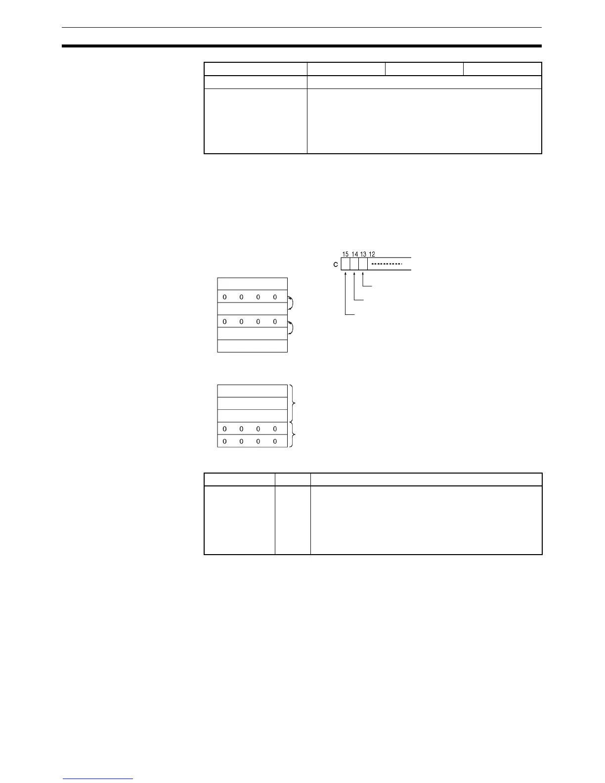
Description When the Shift Enable Bit (bit 14 of C) is ON, all of the words with non-zero
content within the range of words between St and E will be shifted one word in
the direction determined by the Shift Direction Bit (bit 13 of C) whenever the
word in the shift direction contains all zeros. If ASFT(017) is repeated suffi-
cient times, all all-zero words will be replaced by non-zero words. This will
result in all the data between St and E being divided into zero and non-zero
data.
Flags
Precautions When the Clear Flag (bit 15 of C) goes ON, all bits in the shift register, from St
to E, will be reset (i.e., set to 0). The Clear Flag has priority over the Shift
Enable Bit (bit 14 of C).
When St is greater than E an error will be generated and the Error Flag will
turn ON.
Index Registers ---
Indirect addressing
using Index Registers
,IR0 to ,IR15
–2048 to +2047 ,IR0 to –2048 to +2047 ,IR15
DR0 to DR15, IR0 to IR15
,IR0+(++) to ,IR15+(++)
,–(– –)IR0 to, –(– –)IR15
Area C St E
. . .
E
E
. . .
Shift direction
Shift enabled
Clear
Convert
Convert
Non-zero data
Zero data
St
St
Name Label Operation
Error Flag ER ON when St is greater than E.
ON if the Communications Port Enabled Flag for the com-
munications port number specified as the Com Port num-
ber for Background Execution is OFF when background
processing is specified (CP1H only).
OFF in all other cases.
 Loading...


