513
Floating-point Math Instructions Section 3-14
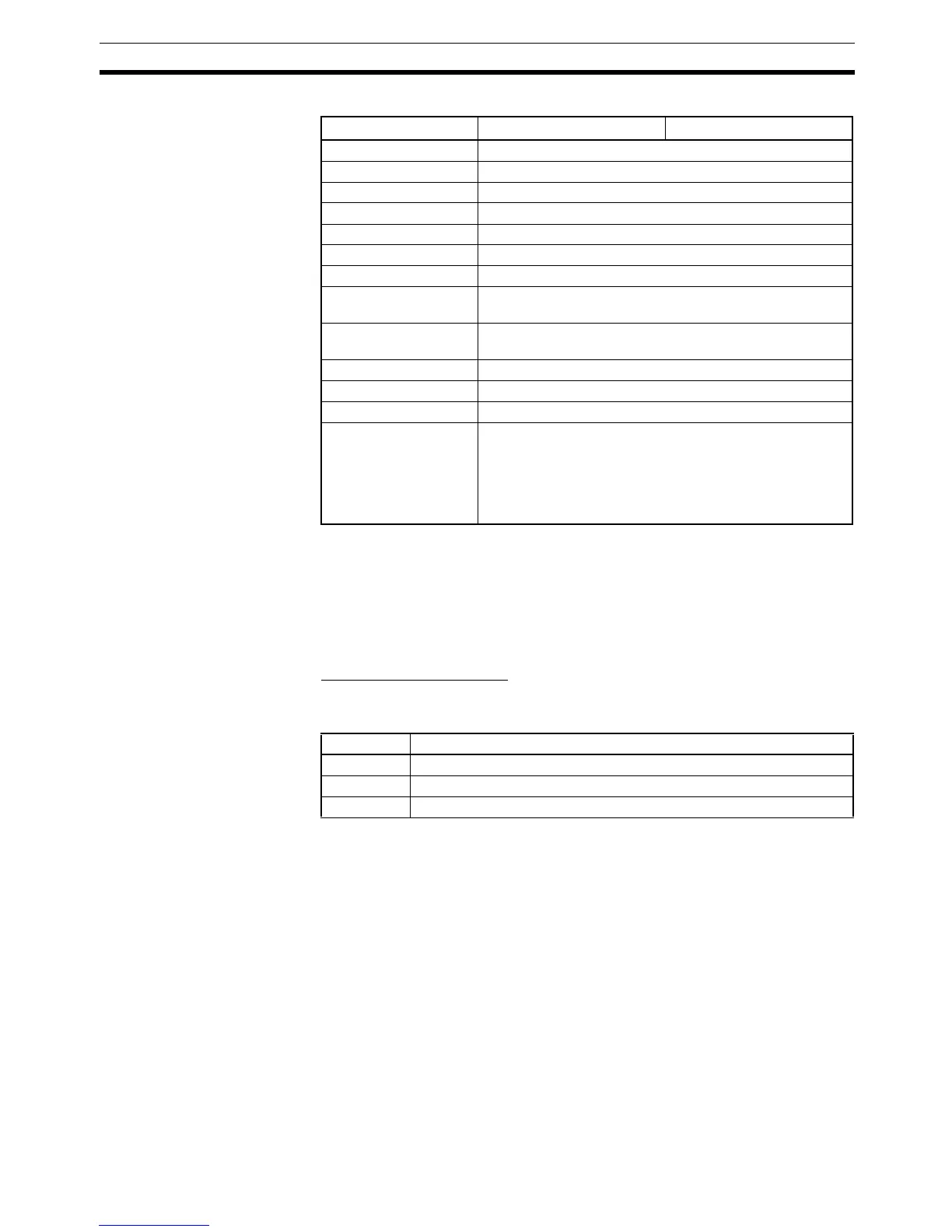
Operand Specifications
Description The input comparison instruction compares the data specified in S
1
and S
2
as
single-precision floating point values (32-bit IEEE754 data) and creates an
ON execution condition when the comparison condition is true. When the data
is stored in words, S
1
and S
2
specify the first of two words containing the 32-
bit data. It is also possible to input the floating-point data as an 8-digit hexa-
decimal constant.
Inputting the Instructions
The input comparison instructions are treated just like the LD, AND, and OR
instructions to control the execution of subsequent instructions.
Area S
1
S
2
CIO Area CIO 0 to CIO 6142
Work Area W0 to W510
Holding Bit Area H0 to H510
Auxiliary Bit Area A0 to A958
Timer Area T0000 to T4094
Counter Area C0000 to C4094
DM Area D0 to D32766
Indirect DM addresses
in binary
@ D0 to @ D32767
Indirect DM addresses
in BCD
*D0 to *D32767
Constants #00000000 to #FFFFFFFF (binary)
Data Registers ---
Index Registers IR0 to IR15 (for unsigned data only)
Indirect addressing
using Index Registers
,IR0 to ,IR15
–2048 to +2047 ,IR0 to –2048 to +2047 ,IR15
DR0 to DR15, IR0 to IR15
,IR0+(++) to ,IR15+(++)
,–(– –)IR0 to, –(– –)IR15
Input type Operation
LD The instruction can be connected directly to the left bus bar.
AND The instruction cannot be connected directly to the left bus bar.
OR The instruction can be connected directly to the left bus bar.