630
Data Control Instructions Section 3-17
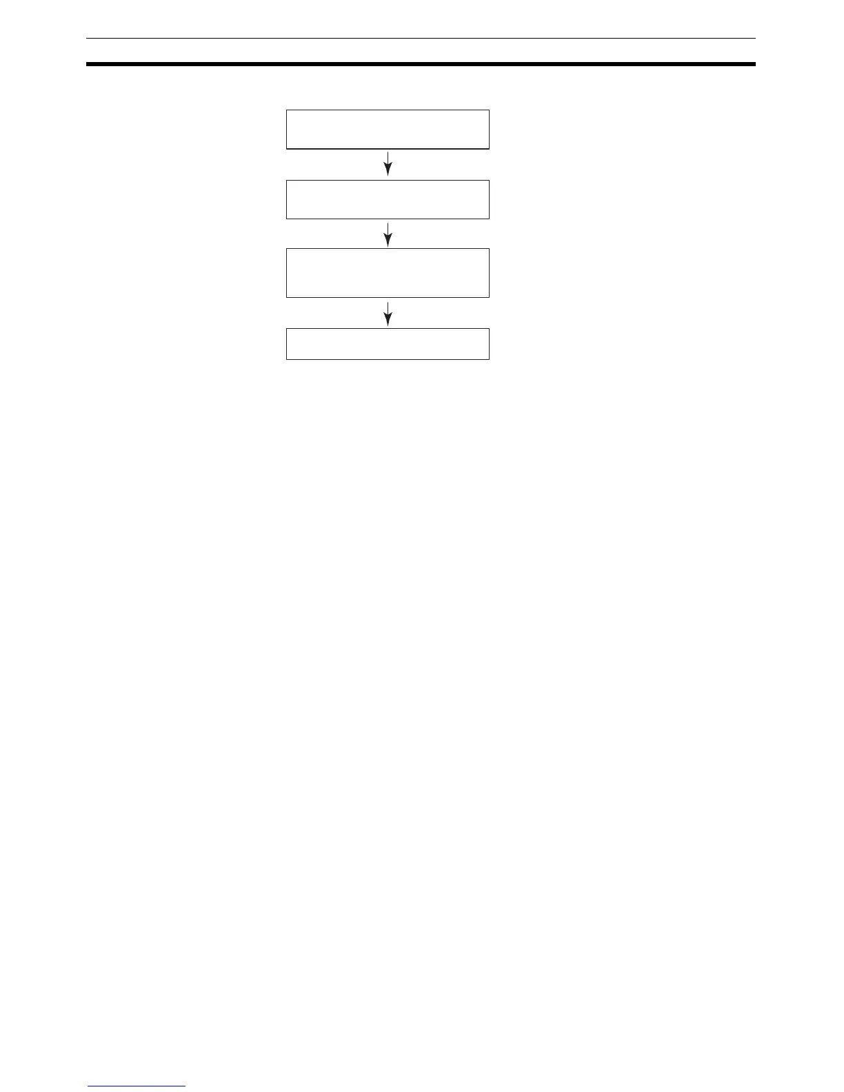
The following flowchart shows the autotuning procedure:
Note (1) If autotuning is interrupted by turning OFF the AT Command Bit during
autotuning, PID control will start with the PID constants that were being
used before autotuning began.
(2) Also, if an AT execution error occurs, PID control will start with the PID
constants that were being used before autotuning began.
In both cases described in notes 1 and 2, the PID constants will be enabled if
they were already calculated when autotuning was interrupted.
PID Control
The number of valid input data bits within the 16 bits of the PV input (S) is
designated by the input range setting in C+6, bits 08 to 11. For example, if 12
bits (4 hex) is designated for the input range, the range from 0000 hex to 0FFF
hex will be enabled as the PV. (Values greater than 0FFF hex will be regarded
as 0FFF hex.)
The set value range also depends on the input range.
Measured values (PV) and set values (SV) are in binary without sign, from
0000 hex to the maximum value of the input range.
The number of valid output data bits within the 16 bits of the manipulated vari-
able output is designated by the output range setting in C+6, bits 00 to 03. For
example, if 12 bits (4 hex) is designated for the output range, the range from
0000 hex to 0FFF hex will be output as the manipulated variable.
For proportional operation only, the manipulated variable output when the PV
equals the SV can be designated as follows:
0: Output 0%
1: Output 50%.
The direction of proportional operation can be designated as either forward or
reverse.
The upper and lower limits of the manipulated variable output can be desig-
nated.
The sampling period can be designated in units of 10 ms (0.01 to 99.99 s), but
the actual PID action is determined by a combination of the sampling period
and the time of PIDAT(191) instruction execution (with each cycle).
The calculated P, I, and D constants are
set in C+1, C+2, and C+3 respectively.
The AT Command Bit is turned OFF.
PID control is interrupted, the MV is
forcibly changed, and the PID constants
are calculated automatically.
The AT Command Bit (bit 15 of C+9) is
ON at the start of PIDAT(191) execution
or it is turned ON during execution.
PID control starts (or restarts) with the
new PID constants.