645
Data Control Instructions Section 3-17
Operands S: Input Word
Specifies the input word containing the input duty ratio or manipulated vari-
able. Bits 04 to 07 of C specify the input type, i.e., whether the input word con-
tains an input duty ratio or manipulated variable. (Set these bits to 0 hex to
specify a input duty ratio or to 1 hex to specify a manipulated variable.)
• Input duty ratio: 0000 to 2710 hex (0.00% to 100.00%)
• Input manipulated variable (See note.): 0000 to FFFF hex (0 to 65,535
max.) (Bits 00 to 03 of C specify the manipulated variable range, i.e., the
number of valid bits in the manipulated variable. Specify the same number
of bits as specified for the output range setting in PID(190).)
Note If S is a manipulated variable, specify the word containing the ma-
nipulated variable output from a PID(190) or PIDAT(191) instruc-
tion.
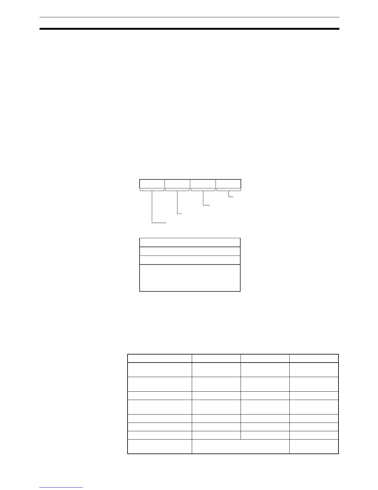
C to C+6: Parameters
The following diagram shows the locations of the parameter data. For details
on the parameters, refer to Parameter Settings in this section.
R: Pulse Output Bit
Specifies the destination output bit for the pulse output.
Normally, specify an output bit allocated to a Transistor Output Unit and con-
nect a solid state relay to the Transistor Output Unit.
Operand Specifications
C+1
C+2
C+3
C+4
C+5
C+6
015
C
815 1211 0347
Manipulated variable range
Input type
Input read timing
Output limit function
Note: For details, see the descri
arameter.
Control period
Output lower limit
Output upper limit
Work area
(3 words, cannot be used by user)
Area S C R
CIO Area CIO 0 to
CIO 6143
CIO 0 to
CIO 6137
CIO 0.00 to
CIO 6143.15
Work Area W0 to W511 W0 to W505 W0.00 to
W511.15
Holding Bit Area H0 to H511 H0 to H505 H0.00 to H511.15
Auxiliary Bit Area A0 to 959 A0 to A953 A448.00 to
A959.15
Timer Area T0000 to T4095 T0000 to T4089 ---
Counter Area C0000 to C4095 C0000 to C4089 ---
DM Area D0 to D32767 D0 to D32761 ---
Indirect DM addresses
in binary
@ D0 to @ D32767 ---
 Loading...


