724
High-speed Counter/Pulse Output Instructions Section 3-20
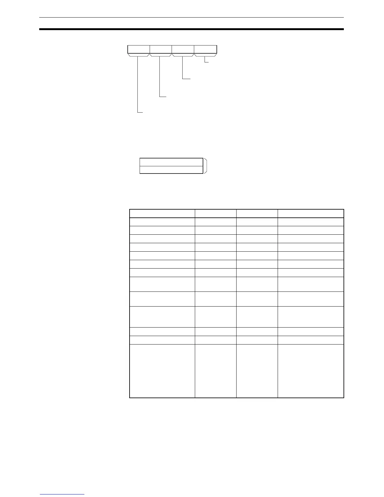
F: First Pulse Frequency Word
The value of F and F+1 sets the pulse frequency in Hz.
Note The maximum frequency that can be specified depends on the model and
pulse output support. Refer to the CP1H Operation Manual.
Operand Specifications
03478
111215
M
Mode
0 hex: Continuous
1 hex: Independent
Direction
0 hex: CW
1 hex: CCW
Pulse output method (See note.)
0 hex: CW/CCW
1 hex: Pulse + direction
Always 0 hex.
Note: Use the same pulse output method when using both pulse outputs 0 and 1 (CP1H only).
F
F+1
0
15
Lower word of target frequency
Upper word of target frequency
0 to 1,000,000 Hz (See note.)
(0000 0000 to 000F 4240 hex)
Area P M F
CIO Area --- --- CIO 0 to CIO 6142
Work Area --- --- W0 to W510
Holding Bit Area --- --- H0 to H510
Auxiliary Bit Area --- --- A448 to A958
Timer Area --- --- T0000 to T4094
Counter Area --- --- C0000 to C4094
DM Area --- --- D0 to D32766
Indirect DM addresses
in binary
--- --- @ D0 to @ D32767
Indirect DM addresses
in BCD
--- --- *D0 to *D32767
Constants See descrip-
tion of oper-
and.
See descrip-
tion of oper-
and.
See description of oper-
and.
Data Registers --- --- ---
Index Registers --- --- ---
Indirect addressing
using Index Registers
--- --- ,IR0 to ,IR15
–2048 to +2047 ,IR0 to
–2048 to +2047 ,IR15
DR0 to DR15, IR0 to
IR15
,IR0+(++) to ,IR15+(++)
,–(– –)IR0 to, –(– –)IR15