732
High-speed Counter/Pulse Output Instructions Section 3-20
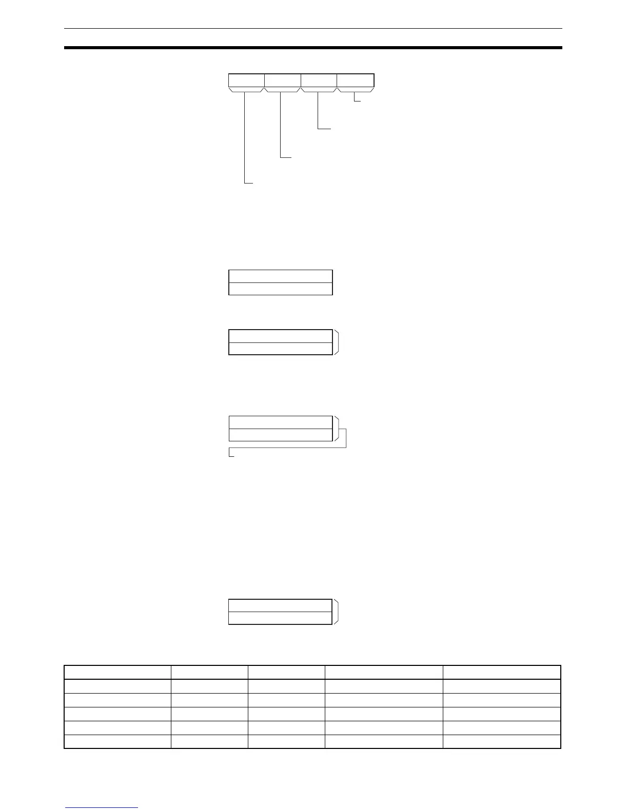
S: First Word of Settings Table
The contents of S to S+5 control the pulse output as shown in the following
diagrams.
The actual number of movement pulses that will be output are as follows:
For relative pulse output, the number of movement pulses = the set number of
pulses. For absolute pulse output, the number of movement pulses = the set
number of pulses
− the PV.
F: First Word of Starting Frequency
The starting frequency is given in F and F+1.
Operand Specifications
03478
111215
M
Mode
0 hex: Relative pulses
1 hex: Absolute pulses
Direction
0 hex: CW
1 hex: CCW
Pulse output method (See note.)
0 hex: CW/CCW
1 hex: Pulse + direction
Always 0 hex.
Note: Use the same pulse output method when using both pulse outputs 0 and 1.
S+4
S+5
S+2
S+3
S
S+1
0
15
Lower word with number of output pulses
Upper word with number of output pulses
Relative pulse output: 0 to 2,147,483,647
(0000 0000 to 7FFF FFFF hex)
Absolute pulse output: -2,147,483,648 to 2,147,483,647
(8000 0000 to 7FFF FFFF hex)
Lower word with target frequency
Upper word with target frequency
1 to 1,000,000 Hz (See note.)
(0000 0000 to 000F 4240 hex)
Specify the frequency after acceleration in Hz.
Acceleration rate
Deceleration rate
1 to 65,535 Hz (0001 to FFFF hex)
Specify the increase or decrease in the frequency per pulse control period (4 ms).
Note: The maximum frequency that can be specified
depends on the model and pulse output support.
Refer to the CP1H Operation Manual.
F
F+1
0
15
Lower word with starting frequency
Upper word with starting frequency
0 to 1,000,000 Hz
(0000 0000 to 000F 4240 hex)
Specify the starting frequency in Hz.
Area P M S F
CIO Area --- --- CIO 0 to CIO 6138 CIO 0 to CIO 6142
Work Area --- --- W0 to W506 W0 to W510
Holding Bit Area --- --- H0 to H506 H0 to H510
Auxiliary Bit Area --- --- A448 to A954 A448 to A958
Timer Area --- --- T0000 to T4090 T0000 to T4094