733
High-speed Counter/Pulse Output Instructions Section 3-20
Upper Limits to the Target
Frequency and Starting
Frequency
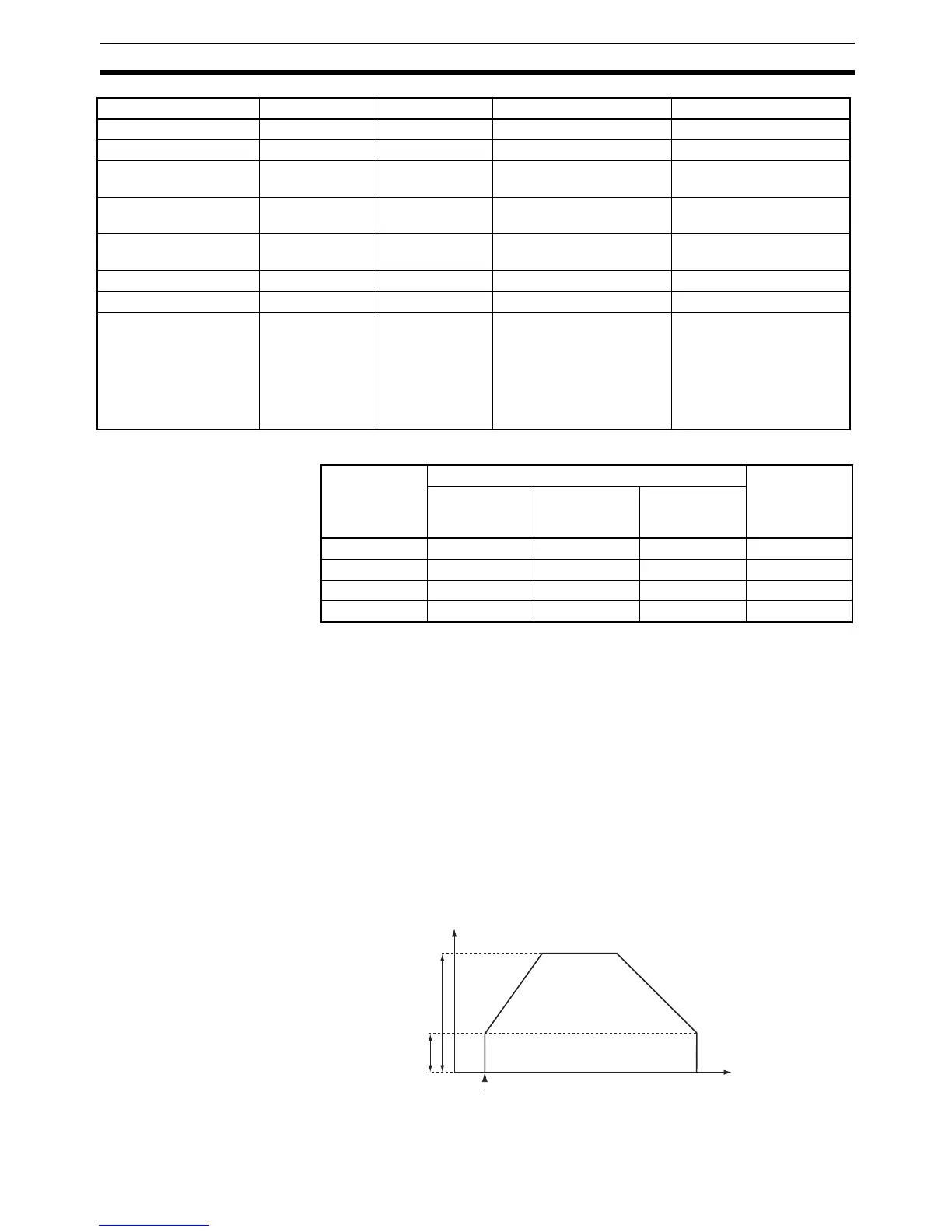
Description PLS2(887) starts pulse output on the port specified in P using the mode spec-
ified in M at the start frequency specified in F (1 in diagram). The frequency is
increased every pulse control period (4 ms) at the acceleration rate specified
in S until the target frequency specified in S is reached (2 in diagram). When
the target frequency has been reached, acceleration is stopped and pulse
output continues at a constant speed (3 in diagram).
The deceleration point is calculated from the number of output pulses and
deceleration rate set in S and when that point is reached, the frequency is
decreased every pulse control period (4 ms) at the deceleration rate specified
in S until the starting frequency specified in S is reached, at which point pulse
output is stopped (4 in diagram).
Pulse output is started each time PLS2(887) is executed. It is thus normally
sufficient to use the differentiated version (@PLS2(887)) of the instruction or
an execution condition that is turned ON only for one scan.
PLS2(887) can be used only for positioning.
Counter Area --- --- C0000 to C4090 C0000 to C4094
DM Area --- --- D0 to D32762 D0 to D32766
Indirect DM addresses
in binary
--- --- @ D0 to @ D32767 @ D0 to @ D32767
Indirect DM addresses
in BCD
--- --- *D0 to *D32767 *D0 to *D32767
Constants See description
of operand.
See description
of operand.
--- See description of oper-
and.
Data Registers --- --- --- ---
Index Registers --- --- --- ---
Indirect addressing
using Index Registers
--- --- ,IR0 to ,IR15
–2048 to +2047 ,IR0 to
–2048 to +2047 ,IR15
DR0 to DR15, IR0 to IR15
,IR0+(++) to ,IR15+(++)
,–(– –)IR0 to, –(– –)IR15
,IR0 to ,IR15
–2048 to +2047 ,IR0 to
–2048 to +2047 ,IR15
DR0 to DR15, IR0 to IR15
,IR0+(++) to ,IR15+(++)
,–(– –)IR0 to, –(– –)IR15
Area P M S F
Port CP1H CP1L
X40/XA40
version 1.0
X40/XA40
version 1.1 or
higher
Y20
Port 0 100 kHz 100 kHz 1 MHz 100 kHz
Port 1 100 kHz 100 kHz 1 MHz 100 kHz
Port 2 30 kHz 100 kHz 100 kHz ---
Port 3 30 kHz 100 kHz 100 kHz ---
A
B
C
D
Target frequency
Starting frequency
Time
PLS2(887) executed.
Pulse frequency