767
Step Instructions Section 3-21
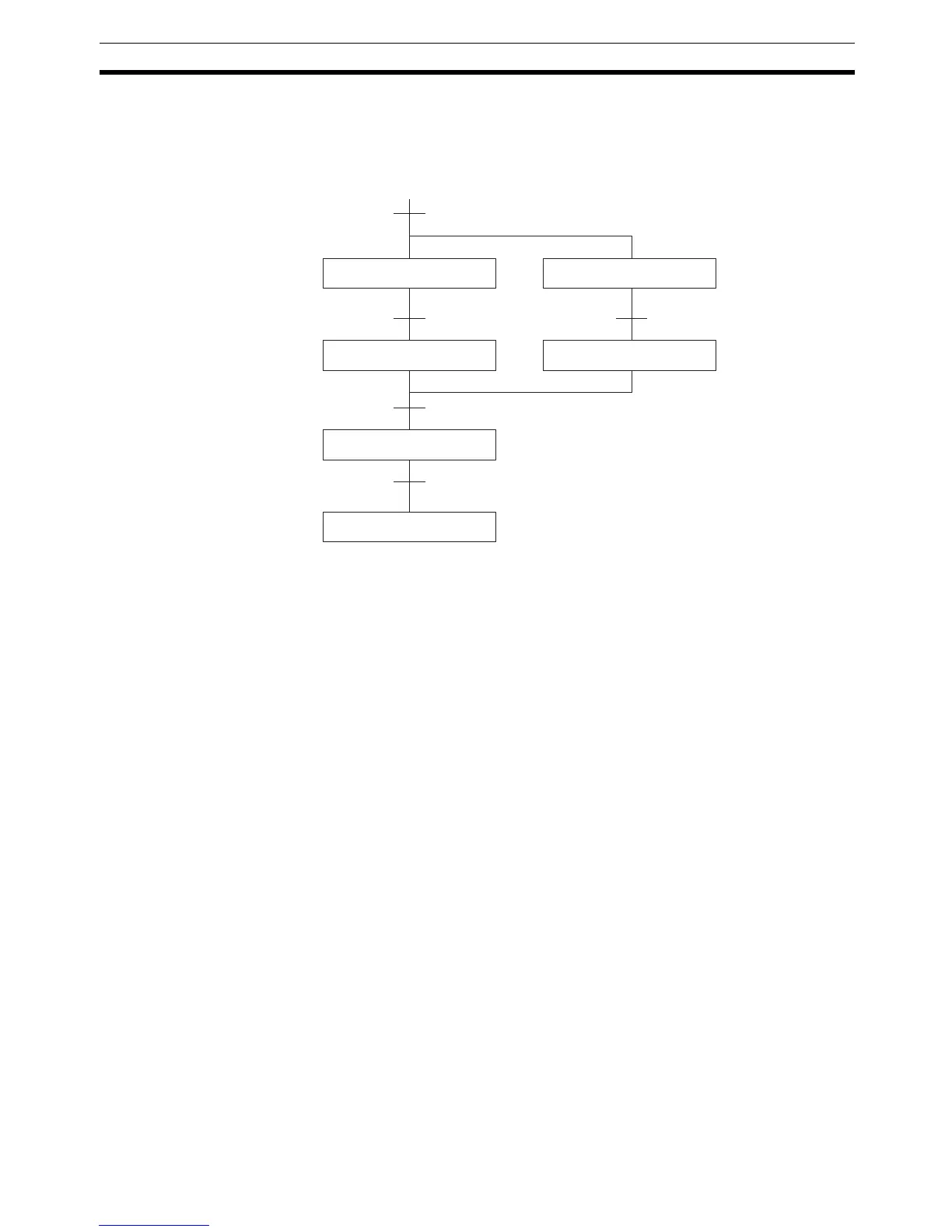
The following diagram demonstrates the flow of processing and the switches
that are used for execution control. Here, process A and process C are started
together. When process A finishes, process B starts; when process C fin-
ishes, process D starts. When both processes B and D have finished, process
E starts.
The program for this operation, shown below, starts with two SNXT(009)
instructions that start processes A and C. These instructions branch from the
same instruction line and are always executed together, starting steps for both
A and C. When the steps for both A and C have finished, the steps for process
B and D begin immediately.
When both process B and process D have finished (i.e., when SW5 and SW6
turn ON), processes B and D are reset together by the SNXT(009) at the end
of the programming for process B. Although there is no SNXT(009) at the end
of process D, the control bit for it is turned OFF by executing SNXT(009)
W0.04. This is because the OUT for bit W0.03 is in the step reset by
SNXT(009) W0.04, i.e., W0.03 is turned OFF when SNXT(009) W0.04 is exe-
cuted. Process B is thus reset directly and process D is reset indirectly before
executing the step for process E.
0.05 (SW7)
0.02 (SW3)
0.03 (SW4)
Process A
Process E
End
Process C
Process B Process D
0.04 (SW5 and SW6 both ON)
0.01 (SW 1 and SW2 both ON)