775
Basic I/O Unit Instructions Section 3-22
3-22-3 DIGITAL SWITCH INPUT – DSW(210)
Purpose Reads the value set on a external digital switch (or thumbwheel switch) con-
nected to an I/O Unit and stores the 4-digit or 8-digit value in the specified
words.
Ladder Symbol
Variations
Applicable Program Areas
Operands I: Input Word (Data Line D0 to D3 Inputs)
Specify the input word allocated to the Input Unit and connect the digital
switch’s D0 to D3 data lines to the Input Unit as shown in the following dia-
gram.
O: Output Word (CS/RD Control Signal Outputs)
Specify the output word allocated to the Output Unit and connect the digital
switch’s control signals (CS and RD signals) to the Output Unit as shown in
the following diagram.
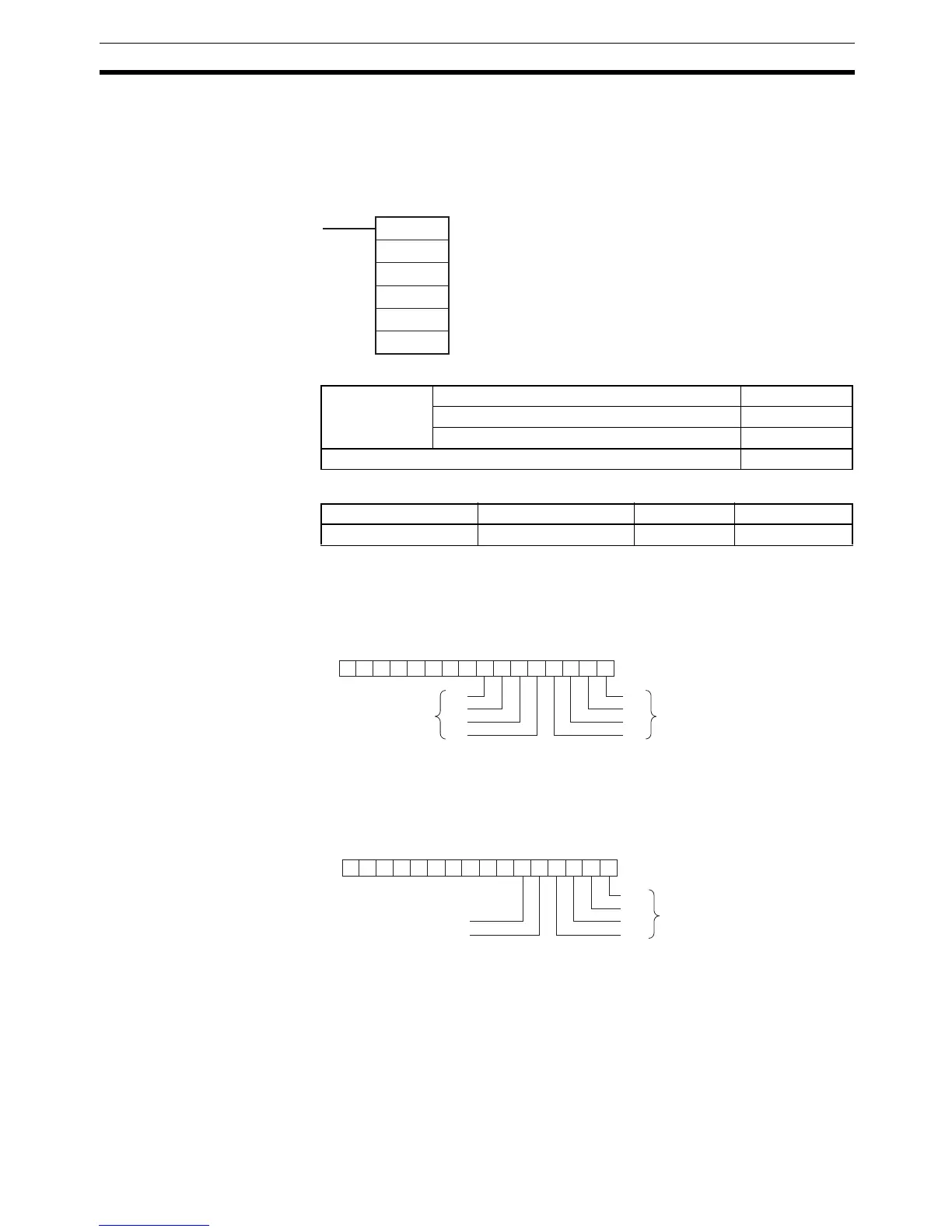
DSW(210)
I
O
D
C1
C2
I: Input word
O: Output word
D: First result word
C1: Number of digits
C2: System word
Variations Executed Each Cycle for ON Condition DSW(210)
Executed Once for Upward Differentiation Not supported.
Executed Once for Downward Differentiation Not supported.
Immediate Refreshing Specification Not supported.
Block program areas Step program areas Subroutines Interrupt tasks
Not allowed OK OK Not allowed
0123456789101112131415
−−−−−−−−
I
D0
D1
D2
D3
D3
D2
D1
D0
Rightmost 4 digit