776
Basic I/O Unit Instructions Section 3-22
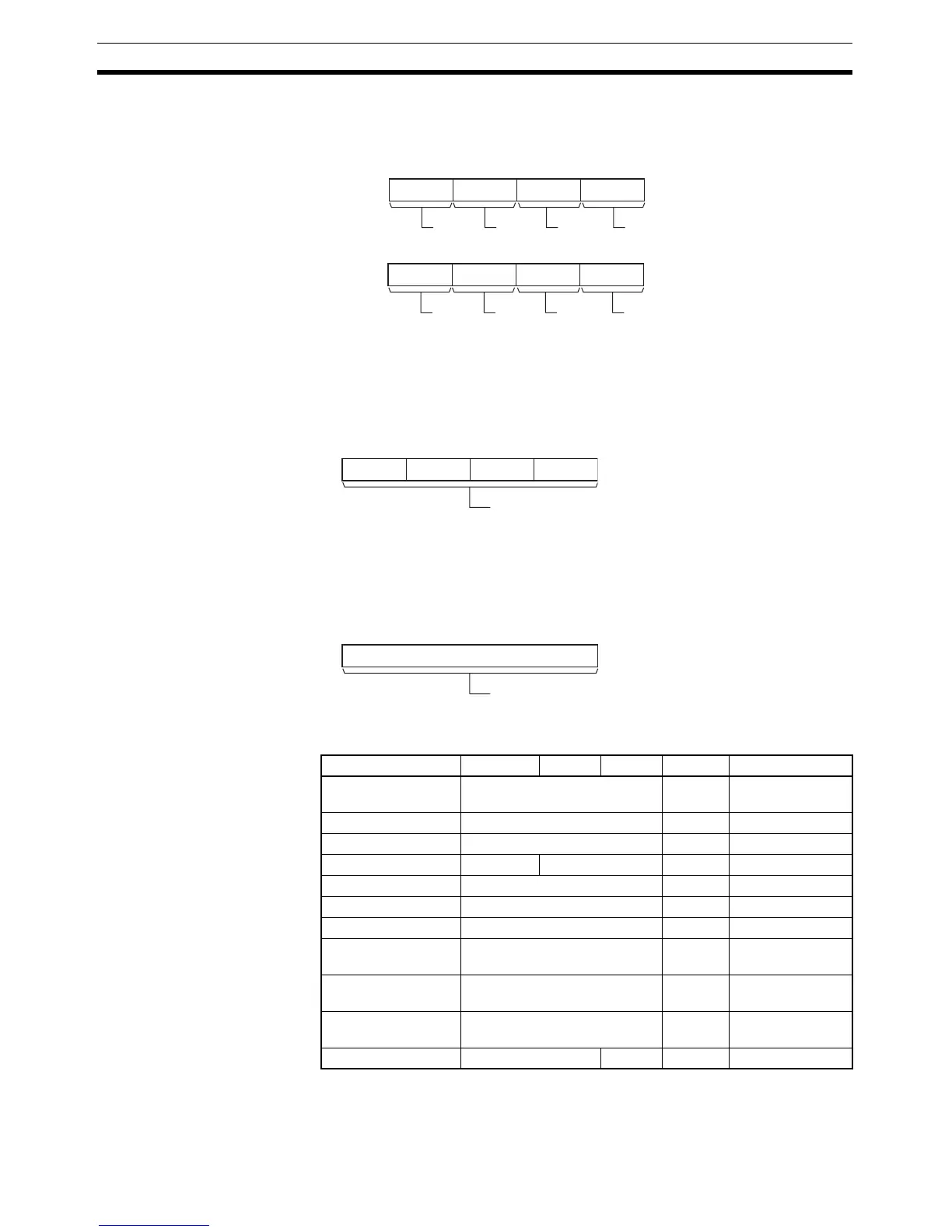
D: First Result Word
Specifies the leading word address where the external digital switch’s set val-
ues will be stored.
C1: Number of Digits
Specifies the number of digits that will be read from the external digital switch.
Set C1 to 0000 hex to read 4 digits or 0001 hex to read 8 digits.
C2: System Word
Specifies a work word used by the instruction. This word cannot be used in
any other application.
Operand Specifications
D
815 1211 0347
D+1
815 1211 0347
Digit 1
Digit 2
Digit 3
Digit 4
Digit 5
Digit 6
Digit 7
Digit 8
Note: Only when C1 = 0001 hex to read 8 digits.
(See note.)
C1
815 1211 0347
Number of digits
0000 hex: 4 digits
0001 hex: 8 di
its
C2
15 0
System word
(Cannot be accessed by the user.)
Area I O D C1 C2
CIO Area CIO 0 to CIO 6143 --- CIO 0 to
CIO 6143
Work Area W0 to W511 --- W0 to W511
Holding Bit Area H0 to H511 --- H0 to H511
Auxiliary Bit Area A0 to A959 A448 to A953 --- A448 to A959
Timer Area T0000 to T4095 --- T0000 to T4095
Counter Area C0000 to C4095 --- C0000 to C4095
DM Area D0 to D32767 --- D0 to D32767
Indirect DM
addresses in binary
@ D0 to @ D32767 --- @ D0 to
@ D32767
Indirect DM
addresses in BCD
*D0 to *D32767 --- ---
Constants --- 0000 or
0001 hex
---
Data Registers DR0 to DR15 --- --- DR0 to DR15