791
Basic I/O Unit Instructions Section 3-22
Operands S: Source Word
Specify the first source word containing the data that will be converted to 7-
segment display data.
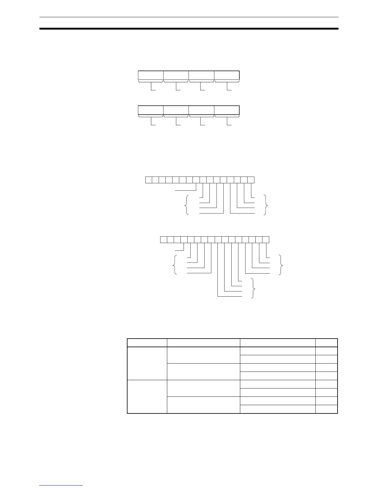
O: Output Word (Data and Latch Outputs)
Specify the output word allocated to the Output Unit and connect the 7-seg-
ment display to the Output Unit as shown in the following diagram.
• Converting 4 digits
• Converting 8 digits
C: Control Data
The value of C indicates the number of digits of source data and the logic for
the Input and Output Units, as shown in the following table. (The logic refers to
the transistor output’s NPN or PNP logic.)
Source data Display’s data input logic Display’s latch input logic C
4 digits (S) Same as Output Unit Same as Output Unit 0000
Different from Output Unit 0001
Different from Output Unit Same as Output Unit 0002
Different from Output Unit 0003
8 digits
(S, S+1)
Same as Output Unit Same as Output Unit 0004
Different from Output Unit 0005
Different from Output Unit Same as Output Unit 0006
Different from Output Unit 0007
S
815 1211 0347
S+1
815 1211 0347
Digit 1
Digit 2
Digit 3
Digit 4
Digit 5
Digit 6
Digit 7
Digit 8
0123456789101112131415
−−−−−−−
O
D0
D1
D2
D3
LE3
LE2
LE1
LE0
4-digit data output
Latch outputs
One Round Flag
0123456789101112131415
−−−
O
D0
D1
D2
D3
LE3
LE2
LE1
LE0
D0
D1
D2
D3
Leftmost 4-digit data outpu