792
Basic I/O Unit Instructions Section 3-22
D: System Word
Specifies a work word used by the instruction. This word cannot be used in
any other application.
Operand Specifications
Description 7SEG(214) reads the source data, converts it to 7-segment display data, and
outputs that data (as leftmost 4 digits D0 to D3, rightmost 4 digits D0 to D3,
latch output signals LE0 to LE3) to the 7-segment display connected to the
output indicated by O. The value of C indicates the number of digits of source
data (either 4-digit or 8-digit) and the logic for the Input and Output Units.
7SEG(214) displays the 4-digit or 8-digit data in 12 cycles, and then starts
over and continues displaying the data.
The One Round Flag (bit 08 of O when converting 4 digits, bit 12 of O when
converting 8 digits) is turned ON for one cycle in every 12 cycles after
7SEG(214) has turned ON each of the latch output signals. After the 7-seg-
ment data is output in 12 cycles, 7SEG(214) starts over and converts the
present contents of the source word(s) in the next 12 cycles.
When executed, 7SEG(214) begins on latch output 0 at the beginning of the
round, regardless of the point at which the last instruction was stopped.
D
15 0
System word
(Cannot be accessed by the user.)
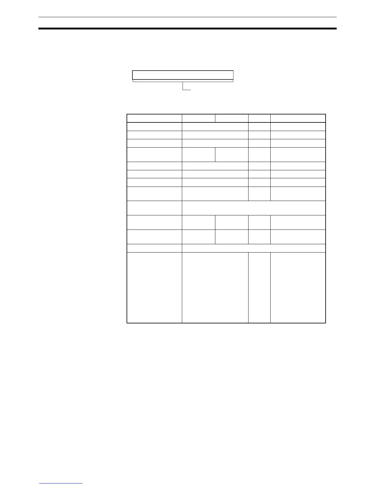
Area S O C D
CIO Area CIO 0 to CIO 6143 --- CIO 0 to CIO 6143
Work Area W0 to W511 --- W0 to W511
Holding Bit Area H0 to H511 --- H0 to H511
Auxiliary Bit Area A0 to A959 A448 to
A959
--- A448 to A959
Timer Area T0000 to T4095 --- T0000 to T4095
Counter Area C0000 to C4095 --- C0000 to C4095
DM Area D0 to D32767 --- D0 to D32767
Indirect DM
addresses in binary
@ D0 to @ D32767 --- @ D0 to @ D32767
Indirect DM
addresses in BCD
*D0 to *D32767
Constants --- --- 0000 to
0007
---
Data Registers --- DR0 to
DR15
--- DR0 to DR15
Index Registers ---
Indirect addressing
using Index Regis-
ters
,IR0 to ,IR15
–2048 to +2047,IR0 to –
2048 to +2047,IR15
DR0 to DR15, IR0 to
IR15
,IR0+(++) to ,IR15+(++)
,–(– –)IR0 to ,–(– –)IR15
--- ,IR0 to ,IR15
–2048 to +2047,IR0
to –2048 to +2047
,IR15
DR0 to DR15, IR0 to
IR15
,IR0+(++) to
,IR15+(++)
,–(– –)IR0 to
,–(– –)IR15