825
Serial Communications Instructions Section 3-23
Examples When CIO 0.00 and the Serial Port 1 Reception Completed Flag (A392.14) is
ON in the following example, data is received from serial port 1 and 10 bytes
of data are stored starting in D100.
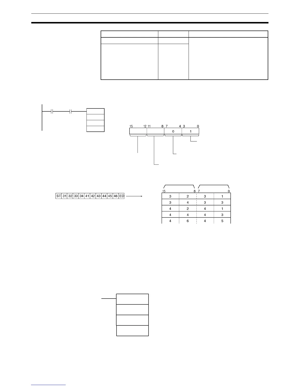
3-23-5 TRANSMIT VIA SERIAL COMMUNICATIONS UNIT: TXDU(256)
Purpose Outputs the specified number of bytes of data from one of the CJ-series Serial
Communications Unit’s serial ports.
Note A CJ Unit Adapter is required to use CJ-series Serial Communications Units.
This instruction can be used in the CP1H CPU Units only. It cannot be used in
the CP1L CPU Units. If TXDU(256) is used in a CP1L CPU Unit, Error Flag
(ER) will be turned ON.
Ladder Symbol
Serial Port 1 Restart Bit A526.01 Turn this bit ON to restart the serial
port. The Reception Completed Flag
and Reception Overflow Flag will be
turned OFF and the Reception Counter
will be cleared to 0.
This bit is turned OFF automatically
when the restart processing is com-
pleted.
Serial Port 2 Restart Bit A526.00
Name Address Contents
C: D200
10
RXD
D100
D200
&10
0.00
D
C
N
A392.14
D: D100
D101
D102
D103
D104
Always 0
Stored
This example assumes that both a start and end
code have been specified in the PLC Setup.
ST: Start code (e.g., 02 hex)
ED: End code (e.g., 03 hex)
Most signifi-
cant bytes
Least signif-
icant bytes
CS and DR signal monitoring
0: No CS and DR signal monitoring
Byte order
1: Least significant bytes first
Serial port specifier
1: Serial port 1 (serial port on Serial Communications
Option Board mounted in option slot 1)
Reception
Completed
Flag
TXDU(256)
S
C
N
S: First source word
C: First control word
N: Number of bytes
0000 to 0100 hex (0 to 256)