826
Serial Communications Instructions Section 3-23
Variations
Applicable Program Areas
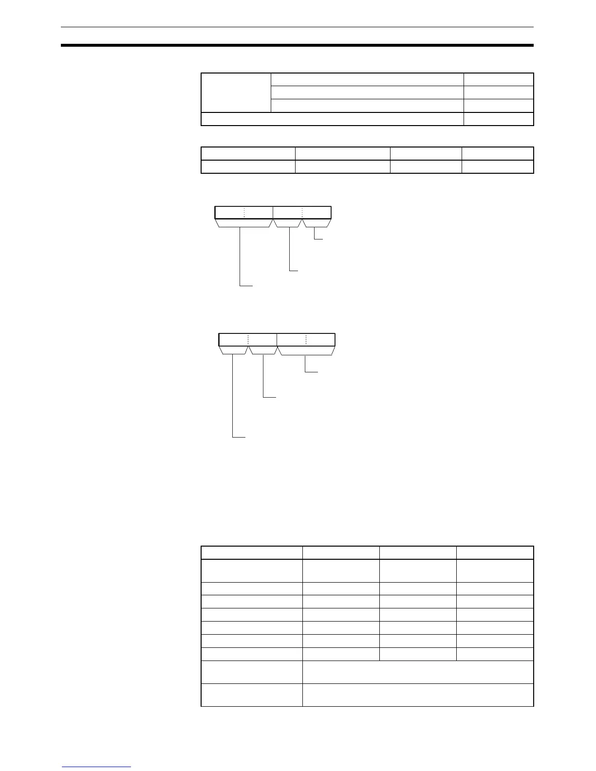
Operands The contents of the control words, C and C+1, are as shown below.
Note The serial port’s unit address can be specified directly by setting the serial
port number to 0 and setting the destination unit address to the serial port’s
unit address. (Set the destination unit address to 80 hex + 4
× unit number for
port 1 or 81 hex + 4
× unit number for port 2.)
Operand Specifications
Variations Executed Each Cycle for ON Condition TXDU(256)
Executed Once for Upward Differentiation @TXDU(256)
Executed Once for Downward Differentiation Not supported.
Immediate Refreshing Specification Not supported.
Block program areas Step program areas Subroutines Interrupt tasks
OK OK OK OK
15 8 011 37 412
C
15 8 011 37 412
C+1
Destination unit address (See note.)
Serial Communications Unit's unit
address (unit number + 10 hex)
Serial port number
0: Specify directly. (See note.)
1: Port 1
2: Port 2
Port number specifier
(Internal logical port)
Specify 0 to 7 or F.
(F: Automatic allocation)
Always 00
Byte order
0: Most significant bytes first
1: Least significant bytes first
RS and ER signal control
0: No RS and ER signal control
1: RS signal control
2: ER signal control
3: RS and ER signal control
Area S C D
CIO Area CIO 0 to
CIO 6143
CIO 0 to
CIO 6142
CIO 0 to
CIO 6143
Work Area W0 to W511 W0 to W510 W0 to W511
Holding Bit Area H0 to H511 H0 to H510 H0 to H511
Auxiliary Bit Area A0 to A959 A0 to A958 A0 to A959
Timer Area T0000 to T4095 T0000 to T4094 T0000 to T4095
Counter Area C0000 to C4095 C0000 to C4094 C0000 to C4095
DM Area D0 to D32767 D0 to D32766 D0 to D32767
Indirect DM addresses
in binary
@ D0 to @ D32767
Indirect DM addresses
in BCD
*D0 to *D32767