840
Serial Communications Instructions Section 3-23
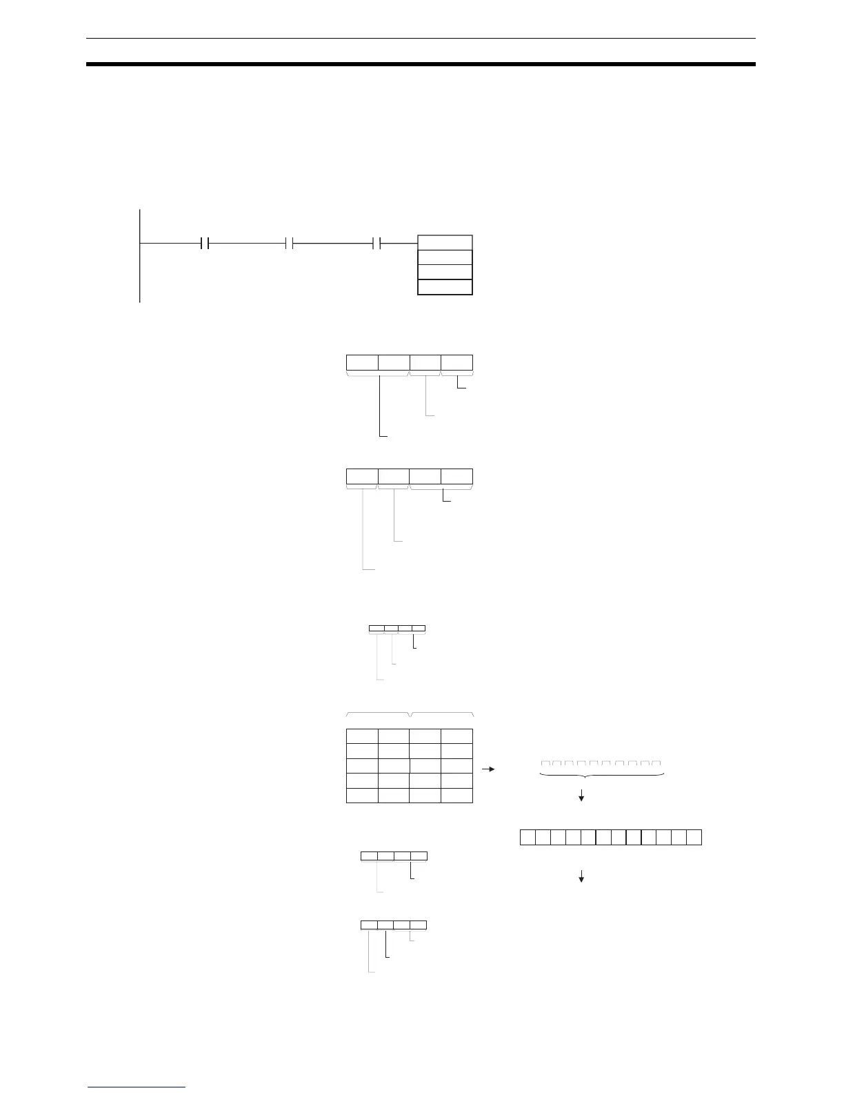
Example: Receiving Data When CIO 0.00 is ON, A202.03 (the Communications Port Enabled Flag) is
ON, and CIO 1559.06 (the Reception Completed Flag for port 1) is OFF in the
following example, RXDU(255) reads the data received through serial port 1
of the Serial Communications Unit with unit number 2. (Logical communica-
tions port number 3 is used to receive the data from a general-purpose device
such as a bar-code reader.) The 10 bytes of received data are written to the
DM Area beginning at the rightmost byte of D100.
RXDU
D100
D200
&10
1559.06
A202.03
D
C
N
0.00
C: D200
0
0 7 815
0
11 12
3
0
Serial Communications Unit's unit address
(CPU Bus Unit's unit address)
12: Unit address + 10 hex
7 815
1
11 12
0 1
4 3
A
lw
ays 0
0: No RS and ER signal control
1 2
4 3
3: Communications port No. 3
Communication port No. specifier (internal logic port)
1: Serial port No. 1
Serial Communications Unit's serial port specifier
D: D100
0 7 815
4 1 2
Most significant bytes Least significant bytes
D101
8 5 6
D102
A
B
1 2 3 4 5 6 7 8 A B C D E F G H I J K L
10 bytes
3412ST 56 78 AB CD
ST: Start code (e.g., 02 hex)
ED: End code (e.g., 03 hex)
Data received
D
3
7
C
H E F
L I J
G
K
D103
D104
EF GH IJ KL ED
C+1: D201
C+1
3
0
88: 80 + (04_Unit No. 2)
7 815
0
11 12
8 8
4 3
3: Communications port No. 3
Communications port No. specifier (internal logic port)
0: Directly specified serial port unit address
Note: Allocated DM Area Settings
• Start code/end code
D30204:
0
End code (e.g., 03 hex)
7 815
2
11 12
0 3
4 3
Start code (e.g., 02 hex)
0
• Start code/end code specifier
D30205:
0 7 815
1
11 12
4 3
1
End code specifier
1: Use end code
00: Unlimited (256 bytes max.)
1: Least significant byte to most significant byte
RS and ER signal control
Serial Communications Unit's serial port unit address specifier
Number of receive data bytes
Start code specifier
1: Use start code
Communications
Port Enabled
Flag
Reception
Completed
Flag
Note: The Serial Communications Unit's serial port unit address can
also be directly specified in C+1.
Received in
specified
order:
Start and end codes added
according to setting in PLC Setup