841
Serial Communications Instructions Section 3-23
3-23-7 CHANGE SERIAL PORT SETUP: STUP(237)
Purpose Changes the communications parameters of a serial port on a Serial Commu-
nications Option Board or CJ-series Serial Communications Unit (CPU Bus
Unit). STUP(237) thus enables the protocol mode to be changed during PLC
operation.
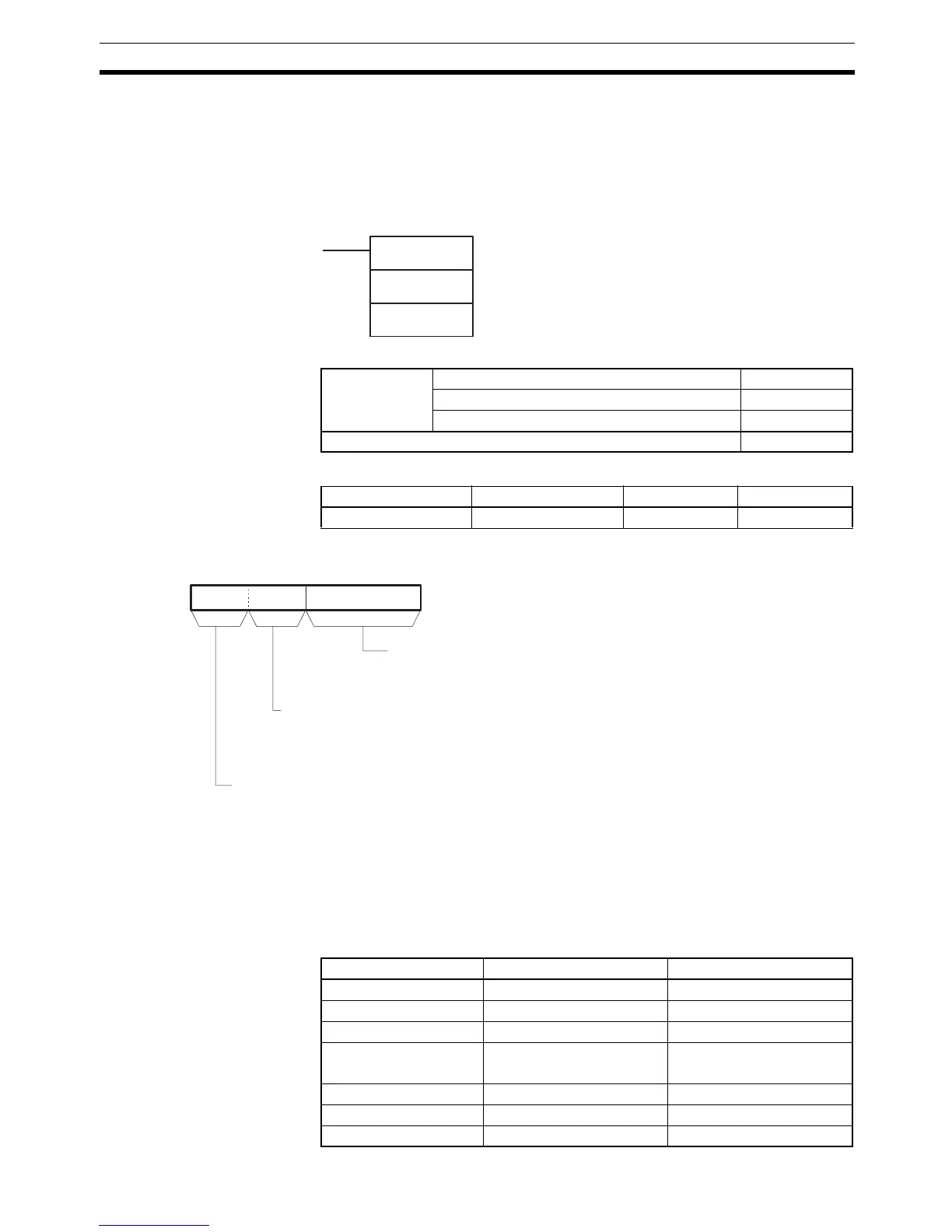
Ladder Symbol
Variations
Applicable Program Areas
Operands The contents of the control word, C, are as shown below.
Note In CP1H and CP1L M (30 or 40 I/O points) CPU Units:
1 hex: Port 1
2 hex: Port 2
In CP1L L (14 or 20 I/O points) CPU Units:
1 or 2 hex: Port 1
0 hex: Invalid setting (The Error Flag will go ON if 0 hex is specified.)
Operand Specifications
STUP(237)
C
S
C: Control word (port)
S: First source word
Variations Executed Each Cycle for ON Condition STUP(237)
Executed Once for Upward Differentiation @STUP(237)
Executed Once for Downward Differentiation Not supported.
Immediate Refreshing Specification Not supported.
Block program areas Step program areas Subroutines Interrupt tasks
OK OK OK Not allowed
15 8 011 712
C
Unit address of partner device
00 hex: Serial Communications Option Board on CPU Unit
Unit number + 10 hex: CPU Bus Unit
Note: In the CP1L, only 00 hex can be set.
Serial port number (See note.)
1 hex: Serial port 1
2 hex: Serial port 2
(Settings 3 and 4 hex are reserved.)
Always set to 0.
Area C S
CIO Area CIO 0 to CIO 6143 CIO 0 to CIO 6134
Work Area W0 to W511 W0 to W502
Holding Bit Area H0 to H511 H0 to H502
Auxiliary Bit Area A0 to A438
A448 to A959
A0 to A438
A448 to A950
Timer Area T0000 to T4095 T0000 to T4086
Counter Area C0000 to C4095 C0000 to C4086
DM Area D0 to D32767 D0 to D32758