958
Failure Diagnosis Instructions Section 3-28
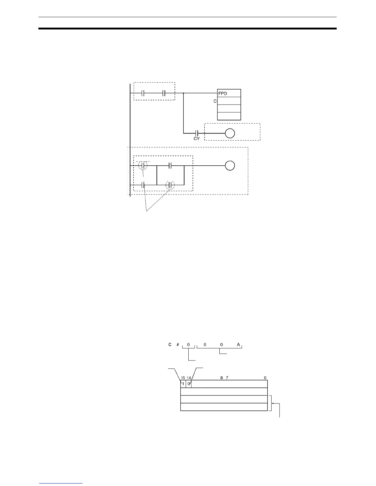
Examples The following program example is used to demonstrate the operation of the
time monitoring function and logic diagnosis function. In this example, the
diagnostic output (CIO 1200.00) does not go ON because CIO 1000.00 and
CIO 1000.03 remain OFF in the logic diagnosis execution condition.
Time Monitoring Function
If the diagnostic output (CIO 1200.00) does not go ON within 10 seconds after
CIO 300.00 and CIO 300.01 are both ON, a non-fatal error will be generated
and the following processing will be performed.
1,2,3... 1. The Carry Flag is turned ON.
2. When the rightmost 3 digits of C specify an FAL number of 00A hex (10),
the corresponding Executed FAL Number Flag (A360.10) will be turned
ON, the corresponding error code (410A) is written in A400, and the FAL
Error Flag (A402.15) is turned ON.
Logic Diagnosis Function (C=000A)
Since the leftmost digit of C is 0 (bit address output mode) the PLC memory
address of CIO 1200.00 is output to D303 and D302. (CIO 1000.00 is on a
higher instruction line than CIO 1000.03.)
T
R
&100
300.00 300.01
D300
2000.00
1000.00 1000.01
1000.02 1000.03
1200.00
Diagnostic output
Execution
condition
Logic diagnosis block
Logic diagnosis execution condition
The diagnostic output (CIO 200.00) remains
OFF because these input conditions are OFF.
Error-processing
block (optional)
R: D300
D301
D302
D303
Not used.
Not used.
Bit Address Found Flag
1: Bit address found
FAL number = 10
Diagnostic output mode = 0 (bit address output)
Input type
0: Normally open
Contains internal I/O memory address.