99
Computing the Cycle Time Section 2-7
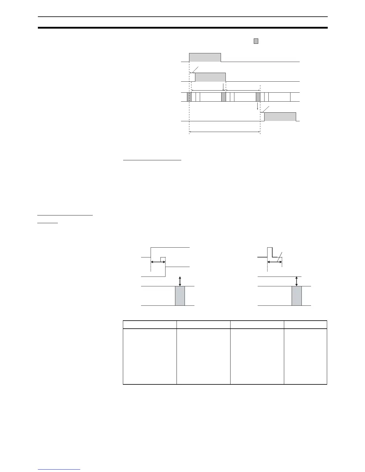
Calculation Example
Conditions: Input ON delay 1 ms
Output ON delay 0.1 ms
Cycle time 20 ms
Minimum I/O response time = 1 ms + 20 ms + 0.1 ms = 21.1 ms
Maximum I/O response time = 1 ms + (20 ms × 2) + 0.1 ms = 41.1 ms
Input Response
Times
Input response times can be set in the PLC Setup. Increasing the response
time reduces the effects of chattering and noise. Decreasing the response
time allows reception of shorter input pulses, (but the pulse width must be
longer than the cycle time).
PLC Setup
2-7-8 Interrupt Response Times
Input Interrupt Tasks The interrupt response time for I/O interrupt tasks is the time taken from when
a built-in input has turned ON (or OFF) until the I/O interrupt task has actually
Input
I/O refresh
Input ON delay
Output ON delay
Cycle time
Cycle time
(Interrupt to
CPU Unit)
Output
Maximum I/O
response time
Instruction
execution
Instruction
execution
Instruction
execution
Input
Input response time
Input
I/O refresh
CPU Unit
CPU Unit
Input response time
The pulse width is
less than the input
response time, so
it is not detected.
Name Description Settings Default
Input constants Input response times 00 hex: 8 ms
10 hex: 0 ms
11 hex: 0.5 ms
12 hex: 1 ms
13 hex: 2 ms
14 hex: 4 ms
15 hex: 8 ms
16 hex: 16 ms
17 hex: 32 ms
00 hex (8 ms)