61
Specifications Section 2-2
Note (1) The load for the above values is assumed to be the resistance load, and
does not take into account the impedance for the connecting cable to the
load.
(2) Due to distortions in pulse waveforms resulting from connecting cable im-
pedance, the pulse widths in actual operation may be smaller than the
values shown above.
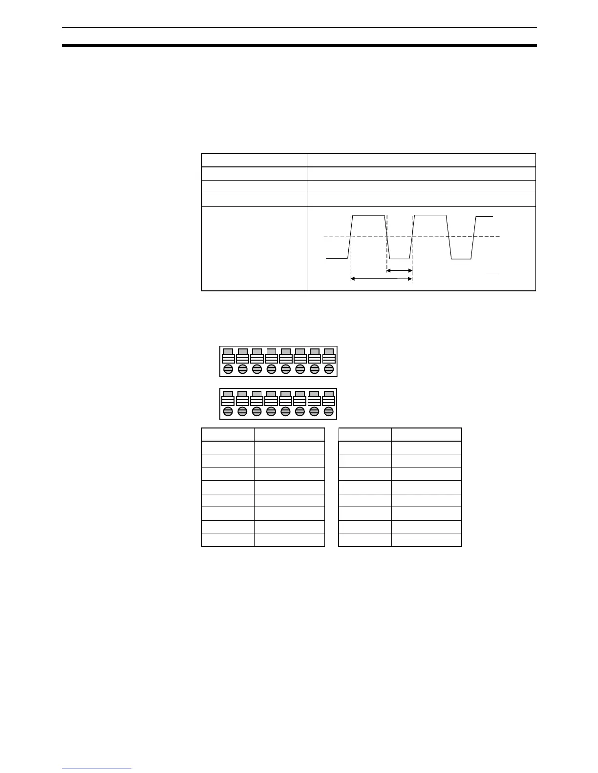
PWM Outputs (CIO 101.00 and CIO 101.01)
2-2-4 Built-in Analog I/O Specifications (XA CPU Units Only)
Analog I/O Terminal Block Arrangement
Note Do not connect the shield.
Item Specification
Max. switching capacity 30 mA/4.75 to 26.4 VDC
Max. output frequency 1 kHz
PWM output accuracy For ON duty +5%, −0%/1 kHz output.
Output waveform
ON
t
ON
T
OFF
× 100%
t
ON
T
ON duty =
Pin Function Pin Function
1IN1+ 9OUT V1+
2IN1− 10 OUT I1+
3 IN2+ 11 OUT 1−
4IN2− 12 OUT V2+
5 IN3+ 13 OUT I2+
6IN3− 14 OUT 2−
7 IN4+ 15 IN AG*
8IN4− 16 IN AG*
A/D
D/A
1234 5678
9 101112 13141516